Scatter_EA
From your first scatter to precise point control.
A practical reference for every object, modifier, and shared workflow.
3ds Max 2027.3 · SEA 0.1258 · 28 topics
Introduction
On this page · 4 sections
What is Scatter_EA?
Scatter_EA is a scattering and point editing tool for Autodesk 3ds Max. Use it to distribute vegetation, rocks, debris, architectural details, or other source geometry across surfaces. You can generate points procedurally, paint them in the viewport, load point caches, convert existing objects to instances, or reference another MAX scene.
A point stores placement and data. Its instance source supplies the geometry. Modifiers then change transforms, choose source shapes, control density, remove overlaps, select subsets, or change display. This lets you work with many placements while reusing geometry.
Your first scatter
- Create a surface and the geometry you want to scatter. Check scene units, source size, and source pivots.
- In the Create panel, open the Scatter_EA category and create SeaPointDistribution.
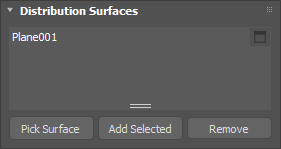
- Add the distribution surfaces to its surface list. Choose a distribution mode and set count, density, or spacing.
- Use the point system’s Point Instance controls to assign your source geometry. A default pyramid is a placement preview until you assign a source.
- Add SeaModify for variation, SeaFilters for masks, or SeaKillOverlaps for spacing between instances.
- Use SeaVisualization to keep the viewport responsive and control the render percentage independently.
Read the stack from bottom to top
The base object creates or imports points. Every modifier receives the result below it. A selection must be below a modifier that uses Selection (below). A transform change before overlap removal changes the tested footprint. A transform change after overlap removal can create new intersections.
PointDistribution → Modify → Filters → KillOverlaps → Visualization. Keep overlap removal on the point data side of the Point Instance workflow, as directed by its rollout.
Find your way around
Choose an object or modifier in the left navigation. Each entry explains its purpose, workflow, and controls. The shared guides describe controls reused across multiple tools.
Controls appear according to the selected mode. A hidden or disabled field usually belongs to another mode. Distances use scene units unless marked otherwise; rotation uses degrees, scale 1 means original size, and percentages describe influence or population.
SeaPointDistribution
On this page · 19 sections
- What this object does
- Workflow
- Choose a distribution mode
- How the modes differ in practice
- Surface list
- Max Items, cancellation, and retry
- Distribution
- Position, Rotation, and Scale variation
- Built-in filters: how they combine
- Slope range: angle-based filtering
- Altitude range: height-based filtering
- Texture range: control coverage with a map
- Texture gizmo fitting and interactive preview
- Distribution map browser: presets, files, and custom maps
- Spline proximity: paths, borders, and clearings
- Geometry proximity: avoid or gather near meshes
- Point proximity: react to another point system
- A practical filter setup
- Point Data Channels
What this object does
SeaPointDistribution generates points on scene surfaces. Choose a mode and set the count, density, or spacing. Use General Filters to restrict the result. CPU is the default. The GPU toggle selects an available backend automatically, with CPU fallback. Its tooltip identifies the active backend or fallback reason.
Workflow
Add meshes to the surface list, select a distribution mode, and adjust population. Assign instance geometry, then add modifiers for variation and filtering. Changing a seed gives a new repeatable layout.
Choose a distribution mode
| Control | What it does |
|---|---|
| Surface (Random) | Samples the actual 3D surface area. Larger triangles receive proportionally more samples, so a dense patch of small polygons does not automatically get more points. Count sets the candidate population across the surfaces. Use this for natural, unstructured scatter on terrain, curved meshes, and walls. |
| UV Grid | Builds a regular lattice in the surface UV layout and maps it back to the mesh. UV Spacing controls the step in texture coordinates. Useful for repeated rows following an unwrap or curved surface. The spacing on the mesh depends on UV scale and stretching: equal UV spacing does not guarantee equal distances in scene units. |
| Grid (Projected) | Builds a grid in world XY and projects down onto the surfaces. Spacing controls its world-space step. Useful for planting rows or even top-view coverage of terrain without relying on UVs. It uses the uppermost hit at each projected location; lower overlapping surfaces and vertical walls are not covered like a full 3D surface scatter. |
| Surface Density | Generates points according to surface density rather than a fixed total Count. The result responds to the area of each surface and is capped by Max points per surface. Use this when multiple terrains should maintain a consistent density as their areas change. Density Jitter perturbs the generated placement. |
How the modes differ in practice
Fixed population or area-based population: Surface (Random) is the clearest choice when you want a chosen total number of candidates. Surface Density is the choice when you want population to follow surface area. The grid modes derive their population from spacing and coverage; the Count field is hidden for them.
UV Grid or projected grid: a UV grid follows the unwrap, so it can wrap around curved geometry and walls. A projected grid follows a world-XY lattice, so it is useful for plan-view spacing across terrain. UV seams, overlapping islands, and uneven texel scale can interrupt UV rows. A projected grid can miss surfaces hidden underneath other surfaces.
Example: use Surface (Random) for scattered stones, UV Grid for repeated details following an unwrapped tube, Grid (Projected) for orchard rows over rolling terrain, and Surface Density for grass coverage on terrains of different sizes.
Filters run on the generated candidates. A requested count or a dense grid is not a guarantee of the same final visible population after masks and overlap removal. Start with a moderate population while tuning masks.
Surface list
| Control | What it does |
|---|---|
| Pick / Add / Remove | Pick a surface, add selected scene objects, or remove highlighted list entries. Removing an entry stops using that surface. |
| Selected faces | Restrict distribution to faces selected on the source Editable Poly or Mesh. |
| Material IDs / Invert | Restrict eligible polygons by their material IDs; invert to use the complementary IDs. |
Picking or adding surfaces works while other rows are disabled. In lists that support multiple objects, use Pick by Name to add all compatible named objects you select.
Max Items, cancellation, and retry
Max Items is a generation safety limit, not the desired visible count or a viewport display limit. A sparse texture can leave few visible points while the underlying potential grid is very large. That grid must still fit the budget.
If the limit is exceeded, the last complete scatter remains visible and the panel reports a warning. Increase Max Items, reduce Point Count or density, or increase Spacing, then edit a setting to generate again. The limit defaults to 2,000,000 candidates.
Press Escape to cancel generation or filtering. Cancellation retains the previous completed output; a new object with no previous result stays empty. Redrawing does not restart cancelled work. Change a distribution setting when you want to retry. An individual third-party conversion or host SDK operation may need to finish before cancellation can be observed.
Distribution
| Control | What it does |
|---|---|
| Mode | Surface (Random), UV Grid, Grid (Projected), or Surface Density. The mode determines which population and spacing fields are shown. |
| Point Count / Count | Candidate population for Surface (Random). Filters can reduce the output. |
| Surface Density / Max points | Density on each source surface and the per-surface cap for density generation. Max Items is an additional overall generation safety budget. |
| Density Jitter | Perturb the density-generated positions. |
| Relax | Smooth random spacing on the surface. 0 disables relaxation. |
| Spacing | Scene-unit spacing for Grid (Projected). Smaller spacing increases the potential grid population. |
| UV Spacing | Grid step in UV coordinates. Resulting world-space spacing depends on UV scale and stretching. |
| Jitter | Perturb grid positions. The selected distribution mode determines the relevant coordinates. |
| Scale | Overall multiplier applied to generated instance scale in every distribution mode, including existing XYZ scale variation. 1 preserves original size. It is animatable; changing it reuses sampled positions. |
| Random Seed / R | Set a repeatable distribution or randomize the seed. |
| Kill Overlaps / Overlap Scale | Enable the creation overlap control and adjust its collision size. Use SeaKillOverlaps for its full methods and per-shape profiles. |
| Direction alignment | Blend between Down, Surface Normal, and Up. The center follows surface normals. |
| Max Items | Maximum sampling candidates before filters; defaults to 2,000,000 and is saved per object. Limits all modes, including UV and density generation. |
| Output points | Completed point count after the base object’s distribution filters and before modifiers above it. During a texture-gizmo drag it keeps the last complete count. |
GPU sampling. Toggle GPU to request acceleration where supported. Read Processing under the point count to see the backend actually used, such as GPU area CDF or CPU. Surface Density and relaxed Random use the CPU.
Position, Rotation, and Scale variation
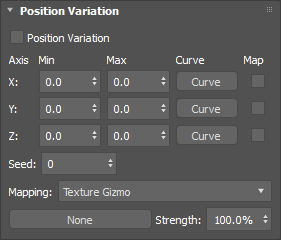
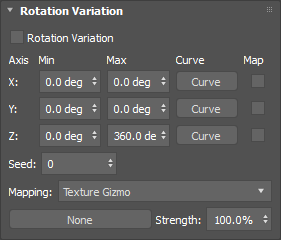
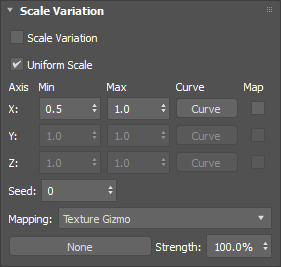
| Control | What it does |
|---|---|
| Enable / axis controls | Enable the transform rollout and edit each available axis range. Position is an offset; Rotation uses degrees; Scale uses multipliers. Equal Min and Max gives a constant value. |
| Uniform scale | Keep proportions when varying size. Disable it to vary axes independently. |
| Distribution / Curve | Choose the axis distribution and edit its remapping curve. The curve maps an input sample to the fraction between Min and Max; it lets you favor small values, large values, or discrete steps. |
| Seed | Choose repeatable variation independently where a transform seed is provided. |
| X / Y / Z Map | Enable the appropriate axis map and assign its driver. Black corresponds to Min and white to Max. Each visible map row has its own mapping and strength. |
| Mapping / Strength | UVs uses the assigned map channel. Texture Gizmo uses the projection gizmo. Strength controls how much the assigned map influences that driver. |
Built-in filters: how they combine
General Filters combines selected faces, Material ID, slope, altitude, and texture masks. Texture uses a brightness threshold. Use SeaFilters for ordered mask operations, proximity, painted boundaries, and shadows.
Slope range: angle-based filtering
Slope measures the angle between the surface normal and world Up. An upward horizontal surface is about 0°, a vertical wall is 90°, and a downward-facing surface approaches 180°. Use it to separate flat ground, steep slopes, cliff faces, or undersides.
| Control | What it does |
|---|---|
| Enable | Activate the Slope range. |
| Min (degrees) / Max (degrees) | Define the angle interval. For example, 0–35° targets relatively flat upward-facing regions, while 65–100° targets steep surfaces. |
| Limited | When checked, values outside Min–Max are excluded. When unchecked, the range is a remapping interval: values below or above it continue using the corresponding curve endpoint rather than being hard-clipped. |
| Min Map / Max Map | Multiply the corresponding numeric angle bound by sampled brightness. The two bounds have independent maps. A black map region drives that bound toward 0; white keeps the full numeric bound. This varies the allowed angle across the surface. |
| Density Falloff / Curve | Use the normalized slope within Min–Max to drive survival. A curve value of 1 keeps full density; 0 removes it. A falling curve thins toward Max. |
| Scale Falloff / Curve | Use a separate curve to multiply instance scale across the slope interval. A constant 1 preserves size; lower values shrink it. |
Example: for grass that fades before a cliff, enable Slope and Limited, set Min to 0° and Max to 45°, then use a Density curve that stays high over gentle ground and falls toward 0 near the steep end. Leave Scale Falloff off if you want surviving plants to keep their normal size.
Reference axis: PointDistribution always measures slope against world Z. Its slope range has no Reference Z picker. Use a Slope entry in SeaFilters when a helper or object should supply a different reference axis.
Altitude range: height-based filtering
Altitude uses the point’s world-space Z height in scene units. It is useful for treelines, shore bands, snow limits, and transitions between low and high terrain.
| Control | What it does |
|---|---|
| Enable | Activate the Altitude range. |
| Min altitude / Max altitude | Define the height interval in the scene’s units. The zero level is world Z = 0, rather than the bottom of each individual surface. |
| Limited | Exclude candidates outside the height interval. Disable it when the curve should continue its endpoint influence outside the interval. |
| Min Map / Max Map | Multiply either height bound by map brightness. This produces a spatially varying height boundary. A zero numeric bound stays zero when multiplied by a map. |
| Density Falloff / Curve | Control population through the normalized height interval. A falling curve favors the low end; a rising curve favors the high end. |
| Scale Falloff / Curve | Independently control size through that height interval. |
Example: to make trees disappear between heights 200 and 300, turn Limited off, set Min = 200 and Max = 300, and use a density curve from 1 at Min to 0 at Max. Below 200 the endpoint keeps full density; above 300 the endpoint keeps zero density. With Limited on, heights below 200 would also be excluded.
For a shoreline band, enable Limited and use a narrow Min–Max interval. Keep Density Falloff off for a uniform band, or enable it and edit the curve to soften coverage within the band.
Texture range: control coverage with a map
Enable Texture range and click the map slot to choose a preset, image, or custom map. Threshold defaults to 50%. Points pass when brightness meets or exceeds the threshold. Invert applies before the test. At 0% every brightness passes. At 100% only white passes. UVs samples the map channel and Texture Gizmo projects using the stack subobject.
Texture gizmo fitting and interactive preview
With Texture Gizmo mapping, select the Texture Gizmo subobject in the stack and use Max Move, Rotate, and Scale. A newly created gizmo fits the world bounds of the distribution surfaces instead of starting at world zero. If no surface is assigned yet, fitting waits until one becomes available. Existing custom gizmo controllers are preserved.
Dragging the texture gizmo uses a temporary random-subsample preview, capped at 100,000 candidates. It can look less dense than the finished scatter. Releasing or cancelling the interaction restores the full result. Output points retains the last complete output count during the drag.
Texture edits reuse cached decisions from unchanged base filters. Changes to source geometry, transforms, mapping, or other relevant settings invalidate the affected cached work. The final result still evaluates the complete population, so a fast drag preview does not imply that a large final update is equally fast.
Distribution map browser: presets, files, and custom maps
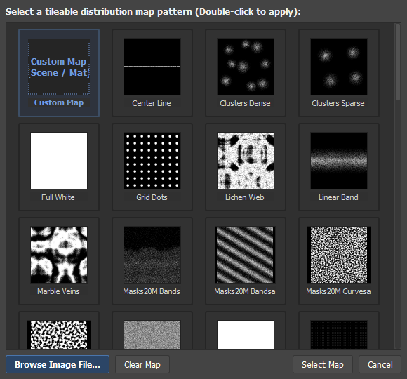
- Enable the texture filter and click its map slot or thumbnail to open the browser.
- Click a preset card once to select it, then click Select Map. Double-clicking a card selects and accepts it in one step.
- Choose Custom Map (Scene / Mat) to open the native map picker and use a scene or Material Editor map.
- Choose Browse Image File… to load a file from disk. The file picker offers PNG, JPG/JPEG, BMP, TGA, TIF/TIFF, EXR, and HDR.
- Click Clear Map to remove the assignment, or Cancel to close without accepting a new choice.
The bundled library includes noise, sparse and dense patches, clusters, stripes, grids, rings, streaks, and other mask patterns. Full White is useful for checking the setup with an unbroken mask before choosing a patterned one.
Where supported, you can also drag an image onto the map thumbnail or a native map onto a map slot. Right-click the main slot to browse or clear it. Range-bound Map buttons use their own image picker and coordinate/weight menu; they modify a numeric bound rather than acting as the main texture density mask.
Spline proximity: paths, borders, and clearings
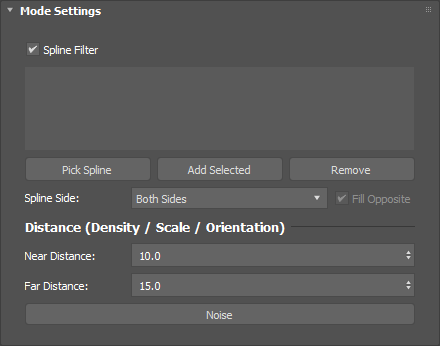
| Control | What it does |
|---|---|
| Enable / spline list | Enable the filter and Pick, Add Selected, or Remove spline references. |
| Both Sides / Outside Only / Inside Only | Use distance on both sides or choose one side of a closed spline. Inside/outside requires a meaningful closed boundary. |
| Fill Opposite | Choose whether the untouched opposite side is filled. Inactive for Both Sides. |
| Density / Near Distance / Far Distance | Enable density control. The normal spline mask keeps the region near the curve, transitioning between Near and Far; Invert reverses the survival mask. |
| Density Curve / Invert | Shape and reverse the density transition. |
| Scale / Near / Far / Curve / Invert | Use independent scale distances and remapping. |
| Scale at Near / Scale at Far | Set the endpoint size multipliers. |
| Distance map / Mapping / Strength / Distance Amount | Vary the distance mask spatially. Mapping and map strength belong to the map; Distance Amount controls its distance modulation. |
Use a spline alongside a path to create a roadside strip, or invert the mask to form a clearing. Start with a hard, easy-to-read distance before softening the transition.
Geometry proximity: avoid or gather near meshes
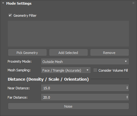
| Control | What it does |
|---|---|
| Enable / geometry list | Choose the reference meshes used for distance tests. |
| Outside Mesh / Inside Mesh / Both Sides | Restrict which side of the reference mesh contributes. |
| Vertex (Fast) | Measure using vertices. This can be coarse on meshes with large faces. |
| Face / Triangle (Accurate) | Measure against triangle surfaces for more accurate surface distance. |
| Hybrid (Balanced) | Use the balanced sampling option between the other methods. |
| Fill volume | Treat the entire interior as full proximity instead of only the shell near the surface. |
| Density Near / Far / Curve / Invert | Normally removes near-reference points. Invert keeps the nearby region instead. |
| Scale Near / Far / Curve / Invert | Configure an independent size transition. Scale at Near and Scale at Far provide the endpoint multipliers. |
| Distance map / Mapping / Strength / Distance Amount | Vary the distance boundary using a map. |
Example: add a building as a reference to clear vegetation around it. Use accurate face sampling if a sparse building mesh produces an uneven clearance.
Point proximity: react to another point system
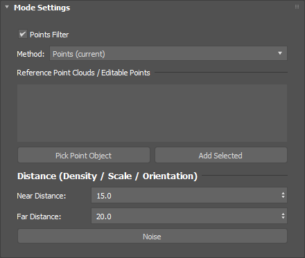
Use a reference point system to create clearances or a second layer of scatter around existing placements. Density and Scale have independent Near/Far distances, curves, inversion, and scale endpoint values, with a distance map where shown.
| Control | What it does |
|---|---|
| Points (current) | Use full 3D distance to reference point centers. Visible point data is used; mesh references can contribute their vertices. |
| Geometry aware (top view) | Use the actual reference instance meshes as cached world-XY footprints, including their scale, orientation, and offsets. Height is ignored. Useful for keeping smaller plants out of tree or rock footprints. |
| Resolution | 64–4096 pixels on the longest side of the footprint map. Increase only when smaller details need to be resolved. Higher values increase memory use and rebuild time. |
| Density / Invert | Normally remove points near the references; invert to keep that neighborhood. |
| Scale at Near / Scale at Far | Size multipliers for the independent scale proximity transition. |
A point-only reference has no mesh footprint. Use Points mode for it, or assign actual reference instance geometry before choosing Geometry aware.
A practical filter setup
- Choose the distribution mode and confirm that points cover the intended surfaces with every filter off.
- Set a repeatable seed and a moderate population.
- Enable Slope to establish the terrain type, then Altitude for the height transition.
- Choose a texture preset and fit its gizmo or UV mapping to break coverage into patches.
- Add spline, geometry, or point proximity for local clearances.
- Inspect scale falloffs separately from density falloffs. If points disappear unexpectedly, disable masks one at a time to find the restrictive one.
Point Data Channels
Store Surface Normal independently from Instance orientation. UV Coordinates, Material ID, Object ID, and Sel. Sets Dist. Surface are optional. The default selection-set prefix is Dist_. An empty prefix uses the surface name. Surface references used by snapping and distribution casters are tracked independently.
SeaPaint · Object
On this page · 17 sections
- What this object creates
- First painting session
- Start, finish, and shortcuts
- Brush modes
- Brush settings
- Data channels: color and custom values
- Creation rollout
- Instanced Geometry: the three source modes
- From list: picking and using a palette
- Physics
- Physics Options
- Understand the two kinds of collision shape
- Physics behavior while painting
- Physics setup: scatter stones on a floor
- Surface constraints, projection, and snapping
- Stroke history and editing safely
- Surface position, orientation, and shortcuts
What this object creates
SeaPaint is a base object that starts a point system from viewport strokes. Create adds placements; the other brushes edit points already in this object. Every point can carry instance geometry, scale, rotation, color, and other data. The Paint modifier uses similar tools on a result coming from lower in the stack.
The following sections explain the controls directly on the Paint object, including its source picker and Physics rollout. Fields change with the active brush, so you only see the settings relevant to that operation.
First painting session
- Create SeaPaint from the Scatter_EA category.
- In Instanced Geometry, choose From list and add a source, or choose Pick Geometry for one source. Check the source pivot and size.
- Choose Create. Set a manageable Radius, Density, Spacing, and Strength.
- In Creation, choose the scale mode and set Randomize Scale, random rotation, and Z offset.
- Click Start Painting and drag over a mesh. Surface hits take priority; otherwise the selected projection plane is used.
- Release to finish a stroke. Use Erase, Move, Scale, or another brush to refine the result.
- Right-click, press Enter, or use the painting toggle to leave the tool.
Start, finish, and shortcuts
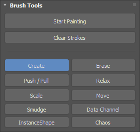
Click Start Painting to enter the viewport tool. Right-click or press Enter to finish; Tab cycles brush modes while painting. Ctrl + Alt + left drag adjusts radius. Alt + left drag adjusts creation Z offset. Modifier keys can have brush-specific behavior; use the tool’s current mode when interpreting a stroke.
Brush modes
| Control | What it does |
|---|---|
| Create | Add points using the chosen source mode. Density sets candidates per stamp; Spacing prevents excessive clustering; Strength controls the probability of accepting each candidate. Shift switches to erasing, and Ctrl switches to Relax. |
| Erase | Hide points locally rather than deleting the point structure. Erase % controls how many are hidden per dose. Holding continues trimming; Shift restores hidden points. Falloff softens the effect toward the brush edge. |
| Push/Pull | Push separates points from the brush region; Shift pulls them toward it; Ctrl relaxes spacing. Radius, Falloff, and Strength control the region and influence. |
| Relax | Spread and smooth local spacing. Strength controls how strongly the spacing is relaxed. Use this to soften a dense hand-painted patch without changing its source choices. |
| Scale | Choose Add, Multiply, Replace, or Subtract. Scale Value is a delta for Add/Subtract, a factor for Multiply, and a target for Replace. Shift reverses Add/Subtract. Ctrl smooths neighboring scale values. |
| Move | Click and drag captured points still inside the brush. Points leaving Radius stop receiving mouse movement; active gravity can continue. Falloff reduces movement toward the edge. |
| Smudge | Move points along mouse travel, weighted by Strength and Falloff. New points join as the moving brush passes over them. Use it to reshape a swath rather than carry only the original captured points. |
| Data Channel | Paint a numeric or color channel. Add, Set, or Multiply uses the Value field; a color channel uses the color swatch. Ctrl averages the values beneath the brush. Shift reverses Add, negates Set, or uses the reciprocal for Multiply. |
| InstanceShape | Reassign instance geometry and its associated source color to existing points in the brush. Choose one or more source variants. Ctrl or Shift in the source list selects multiple entries. |
| Chaos | Agitate Position and/or Rotation, with independent 0–100 strengths. 1 Kick agitates once per press; Continuous Chaos keeps shaking while held. With Physics enabled, it adds linear and angular impulses. |
Brush settings
| Control | What it does |
|---|---|
| Radius | Outer brush radius. |
| Falloff | Inner falloff region controlling transition toward the outer brush edge. |
| Density | Number of candidate points per stamp. |
| Spacing | Minimum spacing while creating points. |
| Strength | Influence of Push/Pull and Relax, or creation probability. Smudge has its own percentage of mouse travel. |
| Erase % | Percentage hidden or restored with each dose, from 0–100%. |
| Brush Shape | Circle, Square, or Sphere. |
| Projection | XY, XZ, YZ, or Screen Space fallback plane. Surface hits take priority. |
| Position / Orientation | Constrain point origins to the recorded surface and optionally align instance orientation to its normal. |
| Force snap | Prefer point hits over surface hits. With this off, point hits are used only if no surface is hit. |
| Preview Points | Show point previews while working. |
| Clear Strokes | Remove the stroke history stored in this object or modifier. |
Data channels: color and custom values
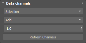
| Control | What it does |
|---|---|
| Channel | Choose an incoming point data channel. Use the Color channel when painting color instead of a numeric value. |
| Axis | X, Y, Z, W, or All. All paints the numeric value on each component. |
| Operation | Add changes by a delta; Set writes a target; Multiply scales the existing value. Falloff blends the result with the incoming value. |
| Value | Numeric operand used by the chosen operation. |
| Color | Color value used for color-channel painting. |
| Refresh Channels | Reload the available incoming channel list after the point data changes. |
Painting a color channel stores point color data. Its visibility depends on the instance display or shading setup; use a color-aware display mode to inspect it. Ctrl averages vector components independently.
Creation rollout
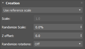
| Control | What it does |
|---|---|
| Use reference scale | Use the selected source’s original scale, including scale captured from a picked SeaXref shape. |
| Override Scale | Set a uniform base scale in the Scale field. |
| Randomize Scale | Vary the base scale independently for each newly created point. A value of 0% keeps the base scale. |
| Randomize rotations: Off | Do not add creation rotation randomization. |
| Randomize rotations: All axes | Add independent random angles to the creation orientation in X, Y, and Z. Useful for stones or debris that can tumble. |
| Randomize rotations: Z axis | Randomize the Z component while retaining the other creation orientation components. Useful for rotational variation without full tumbling. |
| Z offset | Offset new points along their painted surface normal. Positive lifts them away; negative moves them into the surface. Alt + left drag adjusts it while using Create. |
These settings are captured when points are created. Changing the range or offset prepares new strokes; use the Scale or Move brushes when you want to alter existing placements.
Instanced Geometry: the three source modes

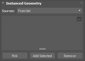
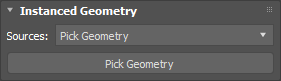
| Control | What it does |
|---|---|
| Incoming/Default | Use the available incoming/default instance geometry rather than choosing a new list or a single picked source. For a new Paint object, the default pyramid provides a placement preview. |
| From list | Maintain a palette of scene objects and select which variants Create or InstanceShape may use. This is the mode for painting mixed vegetation, several rock shapes, or another reusable source collection. |
| Pick Geometry | Pick one scene source through the dedicated Pick Geometry button. The button shows the chosen object’s name. Use this for quickly painting one particular object without maintaining a mixed palette. |
Both Create and InstanceShape use these source choices. Create adds points using a source; InstanceShape changes the source of existing points. Switching source modes does not replace every earlier stroke: earlier placements retain their recorded sources and colors.
When the source is a native Gaussian splat object, Create retains its native type and source orientation. SEA displays a bounding box for the instance in the viewport.
From list: picking and using a palette
- Set Sources to From list.
- Use Pick to collect sources from the scene, or select objects in Max and click Add Selected.
- Select the palette entries you want to paint. A single selection restricts painting to that source. Multiple selections randomize among them per point. If no entry is selected, all listed sources are eligible.
- Use Remove to remove highlighted entries from the active palette.
- Choose Create to add placements, or InstanceShape to paint variants onto existing placements.
The list shows source names and color swatches. During an active Create or InstanceShape stroke, you can hold the mouse button, move over a source in the expanded list to switch objects, then return to the viewport. Recorded earlier sources remain associated with earlier edits.
Pick Geometry uses the single-source picker instead. If you were painting, it pauses for picking and resumes afterward. Keep source geometry available: the palette points to geometry used by the point system.
Physics
| Control | What it does |
|---|---|
| Physics | Enable collision simulation for brush edits and creation settling. |
| Collision | Point, Box, or Convex hull. |
| Collision scale | Multiply collision shape size without changing visible geometry size. |
| Point radius | Scene-unit radius, further multiplied by point scale, object scale, and Collision scale. |
| On create apply it for | Settle only newly created points after release for this number of scene frames. 0 skips settling. |
| Gravity / Magnitude | Downward world-Z acceleration in scene units per second squared. Surface Position constraints remain active with Gravity. |
| Use scene objects | Also collide with geometry visited by the brush. Create remembers surfaces touched during the stroke. |
| Collision objects: Pick / Add / Remove | Manage additional colliders. |
| Geometry: Convex hull | Use solid hulls, placed separately for each point-system instance with its transforms and offsets. |
| Geometry: Mesh | Use triangles, preserving holes and concave surfaces. |
Physics Options
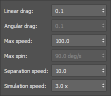
| Control | What it does |
|---|---|
| Simulation speed | Time multiplier for held simulation, 0.1–10×. Default is 3×. It does not multiply gravity or change Create frame duration. |
| Linear drag | Damp translational motion; 0 disables drag. Units are inverse seconds. |
| Angular drag | Damp rotation when orientation is unconstrained. |
| Max speed | Limit linear velocity in world scene units per second. |
| Max spin | Limit angular velocity in degrees per second. |
| Separation speed | Limit overlap-correction velocity. Lower values reduce explosive separation impulses. |
Understand the two kinds of collision shape
Collision: Point / Box / Convex hull chooses the moving painted instance’s collision approximation. Point uses the Point radius. Box uses source bounds. Convex hull follows a solid convex approximation of the source. Collision scale changes the collision shape without resizing the visible instance.
Collision objects → Geometry: Convex hull / Mesh chooses how the supporting or obstructing scene objects are represented. A convex hull is a solid approximation, so it bridges holes and concavities. Mesh follows triangle surfaces and is more suitable for a concave container, an opening, or a detailed support surface. Point-system colliders place the source shape separately at each instance with its scale, orientation, and offsets.
Physics behavior while painting
Physics can resolve collisions during editing, continue simulation while the brush is held, and settle newly created points after the mouse is released. It works with the point edits recorded by the Paint object rather than requiring you to set up a separate timeline simulation.
On create apply it for simulates only newly created points for the specified number of scene frames after release. At 30 fps, 60 frames represents two seconds of settling. A value of 0 skips this stage. Longer frame durations are handled with smaller collision steps.
Gravity accelerates affected points down world Z. The Position constraint remains active with Gravity. Constraint orientation is separate: keep it on when orientation should remain controlled and follow surface normals when constrained; turn it off when debris should tumble through collision-driven rotation.
Use scene objects includes geometry actually hit or visited by the brush. It is not a command to collide with every scene object automatically. Create remembers the touched surfaces during its stroke. Use the explicit collision-object list for additional obstacles or supports that the brush has not touched.
Physics setup: scatter stones on a floor
- Add stone geometry in From list and set Min/Max scale to a modest interval.
- Enable Physics. Choose Box for an initial test, then Convex hull if tighter contact is needed.
- Enable Use scene objects and paint over the floor, or add the floor explicitly to Collision objects.
- Enable Gravity if stones should drop. Disable Constraint orientation if they should rotate naturally.
- Set a short On create frame count and paint a small group. Inspect the settled result before increasing density or duration.
- If separation is too abrupt, reduce Separation speed. If motion takes too long to settle, adjust drag and velocity limits in Options.
Surface constraints, projection, and snapping
Projection selects XY, XZ, YZ, or Screen Space for cases without a mesh hit. A hit surface takes precedence. Force snap reverses the usual priority between point hits and surface hits: enable it to prefer point hits; disable it to use point hits only when there is no surface hit.
Constraint to Surface keeps Move, Relax, and Smudge on their recorded creation surfaces. Missing creation surfaces leave the affected points unchanged. Collision handling happens after that projection; enabling Gravity takes precedence over the surface constraint.
Brush Shape chooses Circle, Square, or Sphere. Start with a small radius to understand the affected region before editing tightly packed or layered placements.
Stroke history and editing safely
Use Clear Strokes to remove the edits stored in this Paint object. In a base Paint object, that can remove the painted placements that build its result. Ordinary undo is useful when testing a brush or an unfamiliar setting.
Creation settings, source choices, and physics motion settings are recorded for new strokes. Changing Physics Options does not resimulate old stroke history. To create a different settled arrangement, undo or clear the relevant test and paint again with the new settings.
The modifier version has additional overall Strength and particle ID matching options. Those are modifier-specific; the base Paint object creates and owns its initial points.
Surface position, orientation, and shortcuts
In Brush Settings, use Position to project touched points onto their recorded surface, including during Physics with Gravity enabled. Orientation aligns instances to the surface normal while preserving heading and scale. The viewport shortcut legend follows the active brush and Max key assignments.
SeaLoader
On this page · 11 sections
Workflow
Browse to a supported point cache, choose sequence handling and units, then assign instances if the file contains only points. Reload after the source file changes. The status area reports the loaded data or a read error.
Supported particle and cache formats
| Control | What it does |
|---|---|
| Alembic · .abc | Point caches in Ogawa archives. Supports animated single-file archives and numbered sequences. This reads point data, not arbitrary Alembic mesh scenes. HDF5 Alembic archives are not supported by the shipped reader. |
| Universal Scene Description · .usd, .usda, .usdc | Reads USD Points primitives and their point attributes, including sampled animation and primitive transforms. Supports single-file animation and numbered sequences. This is a point reader, not a general USD scene or mesh importer. |
| Krakatoa particles · .prt | Reads PRT v1/v1.1 numeric particle channels, typically one file per frame. PRT2 is a different container and is not supported. |
| RealFlow particles · .bin | Reads RealFlow particle BIN layouts 1–12, normally from a frame sequence. The .bin extension must contain that particle format; unrelated binary files are not supported. |
| Bifrost particles · .bif | Reads the supported BIF version 9 particle encoding, including float/vector and uint64 particle arrays. Bifrost volumes are outside this reader’s scope. Nonidentity voxel transforms and unsupported channel encodings are reported as unsupported. |
| tyFlow cache · .tyc | Reads the supported tyCache version 121 particle encoding. Enable Load tyFlow instances to load companion tyMesh prototype geometry when available. The supplied reader does not require tyFlow to be installed. Additional custom property tables or channel schemas may require a reader extension. |
Supported survey, scan, text, and CAD formats
| Control | What it does |
|---|---|
| XYZ / ASCII text · .xyz, .asc, .txt | Reads numeric point rows, with whitespace or comma-separated columns. XYZ position fields are required. Optional named columns can preserve numeric attributes such as color, normals, intensity, and IDs. An arbitrary prose TXT file is not a point file. |
| PTS · .pts | Reads text point data, including the optional initial point-count line. Typical XYZ / intensity / RGB columns are recognized. The declared count is checked against the rows. |
| PTX · .ptx | Reads structured scan grids with registration matrices, intensity, optional RGB, scan membership, row/column indices, and point IDs. Applies the scan registration and excludes zero-position empty samples. |
| PLY · .ply | Reads the vertex point data and numeric vertex properties from ASCII or binary PLY. It does not turn face topology into scattered instance geometry. Ragged/list-valued vertex attributes are not supported. |
| Point Cloud Data · .pcd | Reads ASCII, binary, and binary_compressed PCD, including numeric fields and packed RGB/RGBA where provided. |
| E57 · .e57 | Reads multi-scan point data with Cartesian or spherical coordinates, registration poses, supported numeric attributes, color, and normals where available. Invalid samples are excluded and scans retain identifying information. |
| LAS / LAZ · .las, .laz | Reads LAS survey/LiDAR points and compressed LAZ. Preserves the numeric dimensions available in the source, such as intensity, classification, return information, and RGB when present. |
| AutoCAD drawing · .dwg, .dxf | Reads CAD point entities, or geometry vertices with the CAD import option. Numeric layer/entity metadata and available entity colors are retained. DWG decoding uses the reader runtime supplied with the package. It is not a full drawing-to-instance conversion. |
| Autodesk ReCap · .rcp, .rcs | Reads project or scan point clouds through the host’s ReCap interface. RCP projects must retain access to their referenced scan files. The public host interface exposes positions, RGBA, and normals; other original scan attributes are not available through that route. |
All accepted extensions
.abc .usd .usda .usdc .prt .bin .bif .tyc .xyz .asc .txt .pts .ptx .ply .pcd .e57 .las .laz .dwg .dxf .rcp .rcs
These are the 22 extensions offered by the Loader file picker in the documented build. A supported extension identifies a reader family; a different format variant or unsupported attribute encoding can still produce a diagnostic.
File and time controls
| Control | What it does |
|---|---|
| Path / Browse / Reload | Choose the cache file or refresh it from disk. Supported formats depend on the readers shipped with your host package. |
| Files | Auto detects handling; Sequence reads a numbered sequence; Single archive reads an archive as one source. |
| Time offset | Source time = scene time − offset. A positive offset delays playback. |
| Outside range | Hold the endpoint, Loop the cache, or Hide outside its time range. |
Import controls
| Control | What it does |
|---|---|
| Space | Local applies the loader object’s transform; World interprets source placement in world space. |
| Scale | Multiply imported placement scale. |
| Up axis | Choose +Z or +Y to match the source coordinate system. |
| File units | Auto, Scene units, Meters, Centimeters, Millimeters, Inches, or Feet. Choose explicitly when automatic metadata is absent or incorrect. |
| CAD import | Read Points / point clouds or Geometry vertices. |
| Read every | Read one out of every N source points. 1 loads all points. This changes imported data and is separate from viewport display limits. |
| Load tyFlow instances | Load instance geometry from a tyFlow cache when available. |
Check the result
Before increasing the population, check orientation and size with a known scene object. For animated cache editing, use stable IDs when available so paint edits follow the intended particles.
Single files and frame sequences
Choose Auto for ordinary detection. The loader detects numbered filenames and their padding, and can use matching siblings as a sequence. Use Sequence when the source is explicitly one file per frame, or Single archive to avoid treating a numbered archive name as a sequence.
Alembic and USD can contain animated data inside a single archive. PRT, BIN, BIF, and the supported TYC workflow generally use per-frame files. Missing files inside a sequence produce a diagnostic rather than displaying stale data from a previous frame.
Time offset is measured in frames: an offset of +10 makes source frame 0 appear at scene frame 10. Outside range chooses Hold, Loop, or Hide. These controls affect playback; they do not repair a gap inside a sequence.
CAD and ReCap import tips
CAD import → Points / point clouds reads explicit point entities. Geometry vertices also samples supported CAD entity geometry as vertices or control vertices. If a DWG/DXF contains a point-cloud reference, load the referenced RCP/RCS directly; the CAD route does not resolve that cloud reference into points.
For an RCP project, copy or relink the associated scans as well as the project file. If the host cannot open the scans or exposes an incomplete point set, the Loader reports a failure instead of silently accepting a partial import.
Use File units, Up axis, and Scale to match the survey to your scene. E57 and ReCap supply meter-based unit information; CAD may supply drawing-unit metadata. If a text or other source has no useful unit metadata, choose its units explicitly and compare against a known-sized object.
Geometry, channels, and format limits
A position cache is not automatically an instance-geometry cache. For point-only files, use Point Instance to assign geometry after loading. The tyFlow option is the dedicated route for loading tyCache instance prototypes; keep its companion data accessible.
Numeric channels are preserved where the format and host can represent them. Source IDs remain distinct from Max’s managed point IDs. Unsupported strings, ragged data, or channel encodings are reported rather than treated as ordinary numeric point channels.
If a file fails, read the status message first. Confirm its actual format/version, whether its companion files are present, and whether you selected a point cache rather than a mesh or volume cache. Lower Read every for a denser import, or increase it to load fewer source points while testing.
USD and Storm BIN
USD reads point data, transforms, and numeric channels from USD archives or sequences. Storm RealFlow BIN version 13 sequences retain typed channels and exact 64-bit IDs. Check file mode, Time offset, and Outside range when loading animated caches.
SeaConvertToInstances · Object
On this page · 3 sections
Workflow
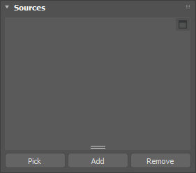
Add geometry to Sources, decide whether to split by element, and enable Detect Similar when independent copies should share matching meshes. Refresh the result after source changes. This object is useful for converting a scene assembly into a compact point system.
All controls
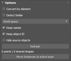
| Control | What it does |
|---|---|
| Sources: Pick / Add / Remove | Build the source list. Pick supports viewport selection and H for selection by name; right-click ends picking. |
| Convert by element | Create placements from separate mesh elements instead of treating each source as one shape. |
| Detect Similar | Find matching meshes across independent copies, including elements, while considering topology, mapping, material, vertices, relative scale, orientation, and pivot offset. |
| World space / Local space | World preserves the original placement when the converter moves. Local applies the converter transform as an additional offset. |
| Keep names | Write point named selection sets from source object names. A source’s elements belong to its set. |
| Keep object ID | Write ObjectID from the source’s 1-based position in the source list. |
| Hide source objects | Hide the original scene objects to avoid showing both originals and converted instances. |
| Refresh | Rebuild the converted result. |
| Move Instances to active layer | Move the actual used shapes to the active layer. It retains the source list and current converted point snapshot for source cleanup. |
| Status | Read conversion counts and diagnostic information. |
Object or modifier?
The object can collect several scene sources and offers World/Local and Hide source objects. The modifier version converts the geometry entering its own stack.
SeaXref (SeaPointRef)
On this page · 5 sections
Workflow
Browse to a MAX file, open Choose Objects to select the required hierarchy entries, then choose Static or Animation. This keeps the source scene external while allowing downstream point modifiers in the host scene.
Reference controls
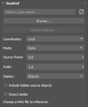
| Control | What it does |
|---|---|
| File / Browse / Reload / Clear | Choose the MAX scene, reload it from disk, or clear the reference. |
| Choose Objects | Choose source objects from the layer hierarchy. Layers open collapsed so you can expand the ones you need. |
| Detect similar | Share matching geometry across source objects that have different transforms or pivots. |
| Mode: Static | Evaluate a specific Source frame using the frame rate stored in the referenced file. |
| Mode: Animation | Follow host frame numbers mapped to the source scene’s frame rate. |
| Scale | Adjust the overall reference scale. |
| Display | Objects displays the contents; Reference Bounding Box gives a lighter preview. |
| Include hidden source objects | Include objects hidden in the referenced scene. |
| Status | Read reference errors, object counts, or shared-shape counts. |
Store Data
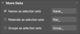
| Control | What it does |
|---|---|
| Names as selection sets | Store source object names as point selection sets. The adjacent prefix field helps distinguish these sets. |
| Materials as selection sets | Store material membership as selection sets, with an optional prefix. |
| Groups as selection sets | Store source group membership as selection sets, with an optional prefix. |
Convenience actions
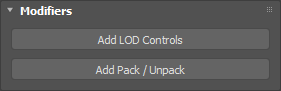
| Control | What it does |
|---|---|
| Add LOD Controls | Add SeaVisualization configured for LOD geometry. |
| Add Pack / Unpack | Add the hierarchy modifier so you can expose nested parts for downstream edits. |
Editing nested parts
If a reference contains nested instance systems, use Pack / Unpack to expose deeper points. Select parts by stored named sets, edit them, and pack them again when the recorded hierarchy is available. Keep the referenced MAX file accessible wherever the scene will be evaluated.
SeaPacking
On this page · 4 sections
Districts and buildings
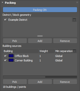
Create SeaPacking under Create → Geometry → Scatter_EA. Add district meshes and building geometry to their respective lists. Each connected mesh element defines a block. Packing starts enabled and computes once both lists contain eligible sources. Use Packing ON/OFF to pause computation, and Repack or commit a changed setting to retry after Escape. Clearing either required list clears the result.
Spacing, weights, and borders
Minimum separation controls footprint clearance in world XY. Zero permits contact and negative spacing permits limited overlap. Per-building Min separation can inherit Global or add a stricter limit. Pair clearance uses the strictest applicable value. Weight is a relative preference and zero excludes a source. Low weights can leave pockets unfilled. Avoid borders uses the complete footprint and includes hole boundaries. Falloff softens the transition. Invert favors the near-border band. Select rows to edit their values together, including direct sources and dynamic rules.
Settings and alignment
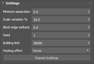
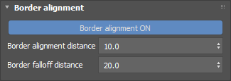
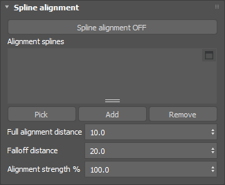
Choose Quick, Standard, or Dense effort, set a seed, scale variation, boundary setback, and building limit. Border alignment starts enabled and follows the nearest edge, including holes, within its alignment distance. Its falloff blends toward world axes. Spline alignment uses the nearest guide tangent in world XY. Set full alignment distance, falloff, and strength. Spline influence blends over the border heading. Numeric edits commit on Enter or spinner release.
Surface contact and point data
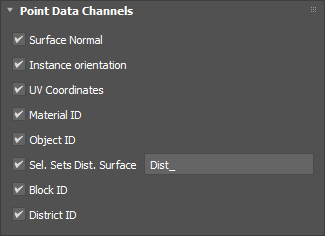
Footprints must fit within their assigned block. The uppermost hit on that block supplies height and Surface Normal while buildings stay upright. Point Data Channels controls Surface Normal, Instance orientation, UV Coordinates, Material ID, Object ID, surface selection sets and their prefix, Block ID, and District ID. District ID identifies the source mesh and Block ID identifies its connected element. Layout depends on available footprints, weights, and alignment.
Packed point data also preserves source wire colors.
SeaModify
On this page · 4 sections
Workflow
Choose Target, enable the required Position, Rotation, and Scale axes, then adjust the ranges. Use a fixed seed for repeatable variation. For a graduated effect, enable weights and use a proximity target or incoming soft selection.
Operation and space
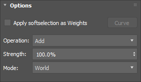
| Control | What it does |
|---|---|
| Target | Choose the points to affect. All shared Target modes are described in the Target guide. |
| Operation: Add | Offset position and rotation, and multiply scale. |
| Operation: Set | Replace enabled values with the generated values. |
| Operation: Multiply | Multiply incoming components by the generated values. |
| Strength | Multiply transform influence after the operation, maps, and selection weights. |
| World / Local | World uses world axes. Local uses each incoming point’s orientation, including instance normal. Point scale does not change position offset distances. |
| Use weights / Curve | Multiply changes by selection weights. Proximity targets supply distance weights; other targets use incoming soft selection. Scale influence blends from multiplier 1. The curve remaps incoming weight to transform influence. Without incoming selected points, the weight option allows full influence. |
Position, Rotation, and Scale
| Control | What it does |
|---|---|
| Axis enables / Min / Max | Enable axes independently and define the generated range. Equal Min and Max produces a constant value. |
| Seed | Each transform rollout has its own variation seed. Change it to regenerate that variation while preserving the other rollouts. |
| Uniform scale | Link scale variation to preserve proportions. Disable it for independent axis scaling. |
| Shared map / axis switches | Use one shared map for a transform rollout and choose which axes it drives. Black drives Min and white drives Max. |
| Mapping / Strength | Use UVs or Texture Gizmo and adjust map influence. UV mode uses the map’s assigned channel. |
Hide controls

Hide hides the Target subset without deleting points. Invert hides the complement while transform variation still uses the original Target. Points already hidden upstream stay hidden. Disable Hide to return to upstream visibility.
SeaFilters
On this page · 23 sections
- Build a filter stack
- Evaluation order and combination operations
- Example: vegetation mask with a clearing
- Enable and disable with eye icons
- Selection, bulk editing, and the expanded list
- Reorder, rename, duplicate, and delete
- Independent entry settings, Target, and Outputs
- Mode selector
- Shared distances and Transform controls
- Splines
- Geometry
- Points
- Occlusion and face-angle regions
- Paint
- Texture entries: Threshold and Invert
- Tileable: repeated mask or one footprint
- Independent named texture gizmos
- Slope and Altitude entries
- Outputs: selection sets, gradients, and keeping points
- Saving and animation
- Shadows
- Orientation modes
- Surface normals and painted falloff
Build a filter stack
Set Target, then click Add Mode and choose a filter. The new row is selected automatically. Configure its Mode Settings and Transform controls, then choose its Operation. The first entry defaults to Set and subsequent entries default to Add. An empty stack passes incoming points through. Use Outputs to write a selection set or gradient or retain the point population.
Evaluation order and combination operations
The list evaluates from bottom to top. The bottom row runs first, followed by the rows above it. Each entry compares its own matching points with the accumulated result:
| Control | What it does |
|---|---|
| Set | Replace the accumulated point membership with this entry’s matches. Use it as a starting mask or to replace earlier mask decisions. |
| Add | Keep points matched by either the accumulated result or this entry: a union. This can restore eligible candidates rejected by earlier rows in this modifier. |
| Subtract | Remove this entry’s matches from the accumulated result. Use it for clearings, paths, or exclusion regions. |
| Multiply | Keep only points matched by both the accumulated result and this entry: an intersection. Use it to restrict an existing mask. |
The accumulator initially contains the incoming points. Therefore a lone Subtract removes its matches, and a lone Multiply keeps its matches. Candidates stay available until the entire entry stack has finished; rejected points are removed once at the end.
Example: vegetation mask with a clearing
Read this example from the bottom row upward:
| Control | What it does |
|---|---|
| Bottom: Texture · Set | Start with patches selected by a Texture entry. |
| Next: Slope · Multiply | Keep only patch points within the allowed slope range. |
| Next: Paint · Subtract | Paint a clearing and remove its matched points. |
| Top: Paint_B · Add | Add another painted region back into the eligible incoming population. |
Move the Add row below the Subtract row and the clearing can remove it again. Add a Set row at the top and it replaces the earlier membership decisions. Use the eye icons to compare the effect of each entry while keeping its configuration.
Enable and disable with eye icons
| Control | What it does |
|---|---|
| Eye before the filter name | Toggle the entry on or off in either the compact or expanded list. Off bypasses all effects of that entry. |
| Settings are retained | Turning an entry off preserves its Set/Add/Subtract/Multiply operation, properties, references, maps, animation, and gizmo. |
| Selected rows | Clicking the eye on a selected row toggles the selected rows together in one undo step. |
| Expanded Enable / Disable | Apply an explicit on/off state to the current multi-selection. |
There is no need to replace a row’s operation to bypass it.
Selection, bulk editing, and the expanded list
Use Ctrl-click to select individual rows and Shift-click to select a range. Opening an operation dropdown captures the current selection. Choosing Set, Add, Subtract, or Multiply changes every selected row in one undo step. The selection remains available for another operation edit; unselected rows keep their operations.
The expanded list has editable Operation dropdowns and bulk controls for operation, Enable/Disable, Up, Down, and Delete. Compact and expanded views share the same row state and stay synchronized through edits and undo. Selecting multiple rows does not turn their Mode Settings into a shared property editor: the active row supplies the displayed entry properties.
Reorder, rename, duplicate, and delete
| Control | What it does |
|---|---|
| Up / Down | Move the selected entry or entries through the list. Evaluation remains bottom to top. Moving multiple rows preserves their relative order. |
| Rename | Use the row’s right-click menu. Bulk rename creates unique names from the supplied base name. |
| Duplicate | Use the right-click menu in either view. Copies appear immediately above their sources and retain operation, on/off state, references, and properties. |
| Independent copies | Duplicated animation and texture-gizmo controllers are cloned. Editing the copy’s settings or gizmo does not edit the source entry. Referenced scene objects remain the same references unless you change them. |
| Automatic names | Repeated types and duplicates use the next unused suffix: Texture, Texture_B, Texture_C; Paint becomes Paint_B. |
| Delete | Remove selected entries through the context menu or expanded controls. Use the eye instead when you want to keep a configuration for later. |
A duplicate can immediately affect the result because it is another evaluated row. For example, duplicating a Subtract entry creates a second subtraction step; inspect its operation and position after copying.
Independent entry settings, Target, and Outputs
Each entry owns its own parameters, references, maps, animated controllers, slope reference, and paint boundary. Selecting a different row switches the property editor to that entry. Two Texture or Paint entries can therefore have different maps, projections, boundaries, and transforms inside the same modifier.
Target belongs to the modifier, not to individual rows. It limits the incoming points the combined filter stack may affect. Points outside Target retain their data. Outputs also belong to the modifier and describe the combined stack result rather than whichever row is currently selected.
Mode selector
Click Add Mode and choose Splines, Geometry, Points, Occlusion, Paint, Texture, Slope, Altitude, or Shadows. The new row becomes active immediately. Use Up and Down to reorder rows, or Delete to remove the selected rows.
Shared distances and Transform controls
For distance-based entries, Near Distance and Far Distance are shared by Density, Scale, and Orientation within that entry. Near is the full-influence region and Far ends its transition. Curve and Noise controls shape that entry’s mask. Different entries can use different distances.
| Control | What it does |
|---|---|
| Reference list / Pick / Add Selected / Remove | Manage the selected entry’s reference objects, splines, or point systems. |
| Density / Density Curve / Invert | Enable density filtering and reshape or reverse its survival mask. Spline filtering normally keeps the near-curve region; geometry and point filtering normally remove their nearby region. |
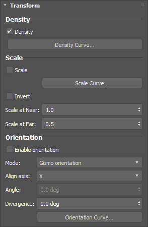
| Scale / Scale Curve / Invert | Enable an independent scale response using the same entry distance interval. Scale at Near and Scale at Far set the endpoint multipliers. |
| Noise | Displace distance sampling to break up a mask boundary. The noise changes mask sampling rather than the actual point positions. |
| Enable orientation | Available for Splines, Geometry, Points, Occlusion, and Paint entries. Enable the directional response for that mask. |
| Max inclination | Maximum tilt angle. |
| Divergence | Random angular variation around the leaning direction, within plus or minus the given angle. |
| Orientation Curve | Remap influence using the shared distance: X = 0 at Far and 1 at Near. |
Texture entries have their own Density, Scale, and Orientation controls. Slope and Altitude provide Density and Scale falloffs with curves.
Splines
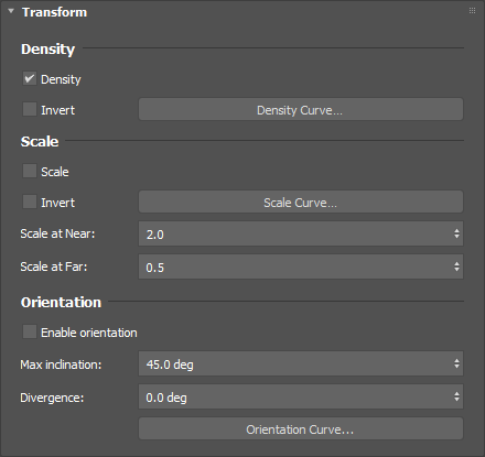
| Control | What it does |
|---|---|
| Both Sides | Measure distance on either side of the spline. |
| Outside Only / Inside Only | Choose the relevant side of a closed spline. |
| Fill Opposite | Fill or empty the untouched opposite side; inactive for Both Sides. |
Geometry
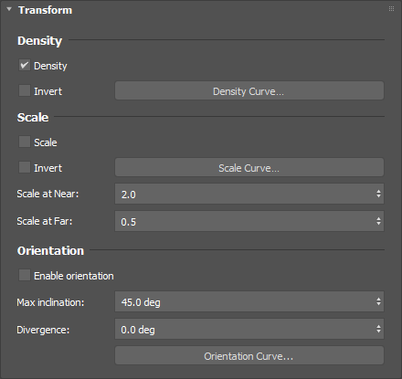
| Control | What it does |
|---|---|
| Outside Mesh / Inside Mesh / Both Sides | Choose where mesh proximity applies. |
| Vertex (Fast) | Approximate distance using vertices. |
| Face / Triangle (Accurate) | Use triangle surfaces for a closer geometric test. |
| Hybrid (Balanced) | Balance surface accuracy and sampling cost. |
| Fill volume | Give the entire mesh interior full proximity, regardless of its distance from the surface. |
Choose Inside Mesh or Outside Mesh to set the side, and enable Fill to use the enclosed volume in the side test. Closed meshes give a defined interior.
Points
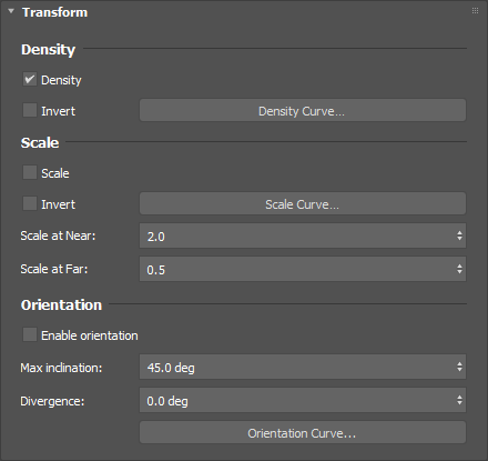
| Control | What it does |
|---|---|
| Points (current) | Use 3D distance to point centers. |
| Geometry aware (top view) | Use cached world-XY footprints of actual reference instance meshes, with their scale, orientation, and offsets. Height is ignored. |
| Resolution | Footprint-map resolution: 64–4096 px on its longest side. Higher values capture finer details at a greater memory and rebuild cost. References without instance geometry contribute no footprint. |
Occlusion and face-angle regions
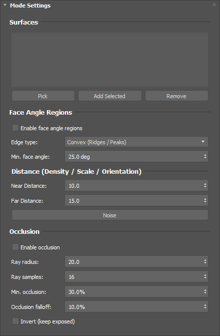
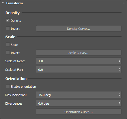
| Control | What it does |
|---|---|
| Shared surfaces | Supply reference meshes for both calculations. An empty list uses the distribution surfaces. |
| Enable face angle regions | Enable filtering around qualifying face edges. |
| Edge type | Convex ridges/peaks, concave valleys/creases, or Both. |
| Min. face angle | Minimum angle between faces that qualifies an edge. |
| Near / Far Distance | Distance transition around qualifying edges. The distance is in 3D world space. |
| Density / Scale / Invert / Curves | Control density and scale independently around these regions. Scale at Near and Scale at Far define the size endpoints. |
| Enable occlusion | Enable the ray-based sheltered/exposed mask. |
| Ray radius | Maximum ray distance in scene units. |
| Ray samples | Rays per point. Higher values improve sampling quality and increase evaluation time. |
| Min. occlusion / Occlusion falloff | Set the threshold and transition width as percentages. |
| Invert (keep exposed) | Keep exposed regions instead of the normally occluded region. |
When you assign explicit occluders, the shared Near and Far distances control the falloff from those casters.
Paint
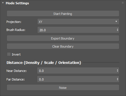
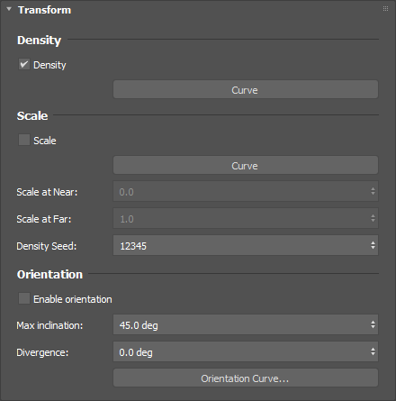
| Control | What it does |
|---|---|
| Start Painting / Brush Radius | Paint the mask in the viewport. Left drag adds; Shift subtracts; Ctrl + Alt + left drag changes radius. |
| Projection | XY, XZ, YZ, or Screen Space. Screen Space stores the captured view plane. |
| Export Boundary / Clear Boundary | Export the painted boundary or clear it. |
| Invert | Reverse the region. |
| Density / Scale / Min / Max / Curves | Use signed distance from the boundary to drive population and size. Positive distance is inside; equal distance limits produce a hard boundary. |
| Scale multipliers / Density Seed | Set the scale endpoints and repeatable random density pattern. |
Use the shared Near and Far values to shape Scale and Orientation even when Density is disabled.
Texture entries: Threshold and Invert
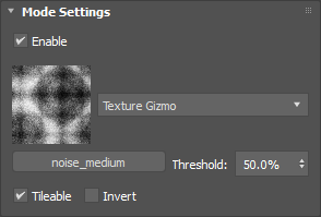
Texture entries use a deterministic brightness Threshold, to select points from the mask. Assign a preset, image, or custom map, choose its mapping, and set the cutoff. Inversion is applied before the threshold test.
| Control | What it does |
|---|---|
| Map slot / thumbnail | Choose a preset or custom map. Use the map browser, file browsing, or supported drag-and-drop workflows. |
| Threshold | Keep points whose sampled brightness is at least this percentage. Default: 50%. Within valid texture coverage, 0% admits every brightness and 100% keeps white. |
| Invert | Reverse brightness before the cutoff: dark areas become bright and bright areas become dark. |
| Tileable | Repeat the image beyond its first tile when on. See the single-tile rules below. |
| Mapping: UVs | Use the channel selected in the assigned map. |
| Mapping: Texture Gizmo | Use this entry’s world-projection gizmo. Select its named subobject in the stack to Move, Rotate, or Scale it. |
| Dimensions / Link X/Y / Offsets / Rotation | Use the coordinate controls where shown. In world-projection mode, transform the entry’s gizmo. |
| Refresh Map | Refresh changed external or custom map content. |
Open Transform to shape Density and Scale with curves. Enable Orientation, then choose Gizmo orientation to align with the projection or Defined angle to enter an angle. Choose the alignment axis and use Divergence to vary the result.
Tileable: repeated mask or one footprint
Tileable is on by default. Turn it off to limit this Texture entry to one transformed world-gizmo footprint or one UV tile. Points outside that footprint do not match the entry, even when Invert is enabled or Threshold is zero. Image-edge sampling is clamped rather than wrapping into the opposite edge.
Example: to make one local patch, turn Tileable off, fit the Texture Gizmo to the desired area, then choose the threshold. To repeat the same pattern over an entire terrain, leave Tileable on.
An outside point failing this entry does not automatically mean it is removed from the final modifier result. Set, Add, Subtract, or Multiply determines how this entry’s non-match combines with the accumulated mask.
Independent named texture gizmos
Each world-projected Texture entry has its own named subobject under SeaFilters. Select the corresponding subobject and transform it with Max’s Move, Rotate, or Scale tools.
Repeated entries are named Texture, Texture_B, Texture_C, and so on. Rename a row to make its gizmo easier to identify; the name updates in the subobject list. UV-projected Texture entries do not expose a world-projection gizmo. Duplicating an entry gives the copy an independent gizmo controller.
Slope and Altitude entries
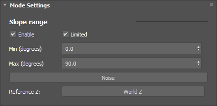
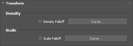
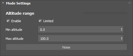
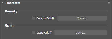
Set Enable, Min, Max, and Limited for the selected range. Slope uses degrees; Altitude uses scene height. Limited clips values outside the interval. With Limited off, values outside use the corresponding falloff-curve endpoint. Density and Scale falloff controls are in Transform; Noise can vary the range sampling.
| Control | What it does |
|---|---|
| Slope: Reference Z | Pick a helper or another scene object. Its normalized local Z axis defines the reference for measuring slope. The picker stays in viewport/H-list pick mode until a reference is chosen or picking is ended. |
| Clear reference / World Z | Clear the reference to return to world (0, 0, 1). |
| Reference transforms | Rotating the reference changes the slope direction and therefore the matched points. The reference belongs to this entry. |
| PointDistribution comparison | The base PointDistribution slope range always uses world Z and has no Reference Z picker. Use a SeaFilters Slope entry for a custom axis. |
| Density / Scale Falloff / Curves | Remap the normalized range independently for population and size. |
| Noise | Break up the range boundary without adding a range-bound image map. |
For a treeline fade, use an Altitude entry with Limited off, Min and Max defining the transition, and a Density curve falling from 1 to 0. For a slope test relative to a tilted structure, pick that structure or a helper as Reference Z in a Slope entry.
Outputs: selection sets, gradients, and keeping points
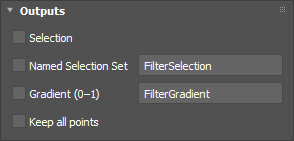
| Control | What it does |
|---|---|
| Selection | Write the combined membership to the active point selection. |
| Named Selection Set / name | Save the combined membership as a named set for downstream Target controls. |
| Gradient (0–1) / channel name | Write a float channel describing the combined gradients. Use it for downstream weighting or inspection. |
| Keep all points | Keep the incoming population instead of removing points rejected by the combined filter. Useful when exporting a mask for later processing. Transform effects still apply where configured. |
The selection set describes the evaluated membership. The gradient combines the entry gradients using the corresponding clamped arithmetic operation; it need not equal a binary density decision at every point. Outputs are taken from the whole stack, not from the active row’s preview alone.
Saving and animation
Entry settings, enabled states, references, animation, and independent gizmos survive save/load, undo/redo, and modifier cloning.
Select a row to show its property editor. A new modifier shows Target and Mode until you add and select an entry. Multi-row operation edits preserve the selection in both list views.
Shadows
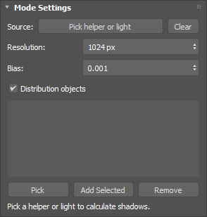
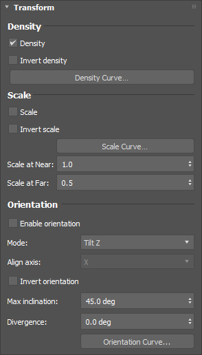
Pick one helper or light as the source. Helpers and directional lights cast parallel shadows. Spot and omni lights use perspective depth maps, and spot cones limit coverage. Distribution objects supplies casters by default. Pick additional mesh geometry in the caster list. Turn Distribution objects off to use only that list. Resolution defaults to 1024 px. Soft edges feather the mask and Invert keeps lit points. Casters use opaque evaluated geometry.
Use the Falloff rollout to set Near and Far up to 2,000 px. In Transform, Density and Scale each have their own inversion and curve. Scale at Near and Scale at Far set the endpoint values.
Orientation modes
Enable Orientation and choose Tilt Z, Acquire Local Axis, Orient to Closest Point, or Orient to Tangent. Choose X, Y, or Z alignment and use Invert to reverse direction. Closest Point works in world XY. Mesh tangent uses the surface normal crossed with world Z. Painted boundaries use their projection frame and nearest edge. The shared Near/Far distances give full influence near the source and zero far away. Curve and Divergence apply across modes. Max inclination applies to Tilt Z. Spline orientation follows the selected side and Fill setting.
Surface normals and painted falloff
Slope defaults to Surface Normal. Pick another Normal channel to evaluate instance orientation, a stored vector, or the local Z axis of a quaternion or transform. Missing default surface metadata falls back to instance normals. An explicitly selected missing channel leaves slope unapplied. For Paint, choose Inside or Outside. Outside keeps the filled interior at full influence and fades outward from the boundary. The setting applies to density, scale, and orientation.
SeaPaint · Modifier
On this page · 4 sections
When to use it
Add this modifier above PointDistribution, Loader, Convert to Instances, or PointRef to refine an existing result. Choose Target to restrict existing-point edits. Use Target: All when creating new points.
Brushes and rollouts
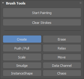
Use the same brushes, Creation, Instanced Geometry, and Physics controls as the Paint object. The shared Painting & Physics guide lists them. Clear Strokes removes the edits recorded in this modifier.
Modifier options
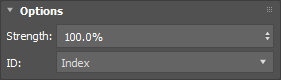
| Control | What it does |
|---|---|
| Strength | Multiply the influence of all edits stored in this Paint modifier. |
| ID | Choose the point channel used to match particles across evaluations. New modifiers default to Index. Choose a stable ID channel when the upstream point order can change. Missing or duplicate keys are skipped. |
Animated and changing sources
Stable IDs help keep edits attached to the intended particles. Index follows point order, so a source whose ordering changes can produce a different match. Earlier strokes retain their recorded instance sources and colors even when you change the current geometry list.
SeaXref supplies live references for Paint, including updates to imported layers and instance colors. The Creation rollout uses the reference scale and override controls described under SeaPaint Object.
SeaKillOverlaps
On this page · 4 sections
Workflow
Assign your instance sources, finalize the important scale and rotation variation, then add this modifier where the overlap rollout directs in relation to Point Instance. Choose a collision method and inspect the surviving layout with full geometry or bounds.
Collision controls
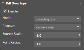
| Control | What it does |
|---|---|
| Enable | Turn overlap removal on or off. |
| Mode: Bounding Box | Test oriented source bounds. Fast and predictable, but empty space inside the box still counts. |
| Mode: Convex Hull | Use the source’s convex hull for a tighter solid approximation. |
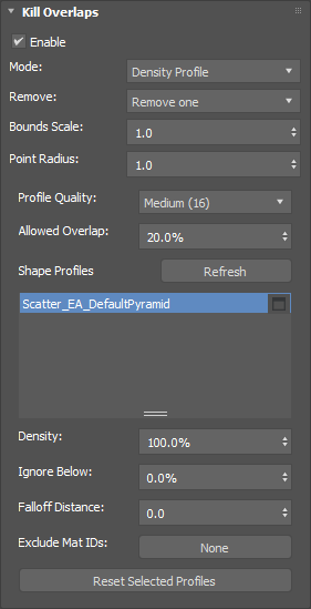
| Mode: Density Profile | Estimate occupied volume with cached per-source profiles. Useful for irregular or sparse vegetation. |
| Remove one | Keep the first surviving placement in the tested order. |
| Remove both | Remove both members of an overlap. |
| Remove larger first / Remove smaller first | Prioritize removal using transformed bounding-box volume. |
| Bounds Scale | Multiply collision size about the source bounds center. 1 uses the original size. This changes collision size rather than displayed geometry. |
| Fallback Radius | Radius for a point without assigned instance mesh geometry. |
Density Profile settings
| Control | What it does |
|---|---|
| Profile Quality | Low (8), Medium (16), or High (32) source-relative grid resolution. Higher values capture more gaps and cost more preparation and overlap work. |
| Allowed Overlap | Cumulative overlap budget for the smaller occupied profile. 0% rejects occupied-cell intersections; 100% allows all profiled shapes. |
| InstanceShape list | Select one or more source slots to edit their overrides together. Overrides follow the selected slots. |
| Density | Multiply the occupancy estimate, from 0–400%. Lower values suit sparse plants or alpha-cutout cards. 0 excludes a shape from density overlap checks. |
| Ignore Below | Ignore the lower percentage of source bounds height; useful for canopy-only profiles. |
| Falloff Distance | Outside the occupied profile, progressively remove nearby point positions with stable randomness. 0 disables this extra falloff. |
| Exclude Mat IDs | Choose material IDs to exclude from profile voxelization and falloff. None includes all faces. |
What to expect
Profiles estimate geometric occupancy. Adjust Density for leaf cards whose mesh surface overstates visible coverage. A later modifier that enlarges or moves instances can reintroduce intersections, so stack order matters.
SeaClusters
On this page · 5 sections
Workflow
Assign several instance sources, refresh the source-color list, and choose a mode. Clusters creates patches of variants; distance modes arrange sources from near to far; Paint lets you directly choose local variants.
Diversity controls
| Control | What it does |
|---|---|
| Enable / Target | Enable the operation and restrict the affected points. |
| Mode | Clusters, Match Color ID on Map, Paint, From object distance, From spline distance, or From target. |
| Seed | Repeatable source distribution. |
| Refresh Point Instance Colors | Reload source entries and their colors from the incoming instance table. |
| Move Up (Near) / Move Down (Far) | Reorder variants for distance assignment. |
| Group by instance color / Hue | Group similar hues within the chosen percentage of the hue wheel. 5% equals 18 degrees. Grays form a separate group. Variants retain their probabilities. |
Clusters and map controls
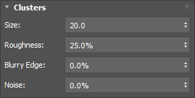
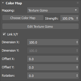
| Control | What it does |
|---|---|
| Size | Size of the spatial patches. |
| Roughness / Blurry Edge / Noise | Control patch irregularity and transition softness. |
| Color Map / Strength | Choose the map used for color matching and its influence. |
| Mapping | UVs or Texture Gizmo. |
| Link X/Y / Dimension X/Y | Set and optionally link projection dimensions. |
| Offset X/Y / Rotation | Position and rotate the map coordinates. |
Distance and Paint
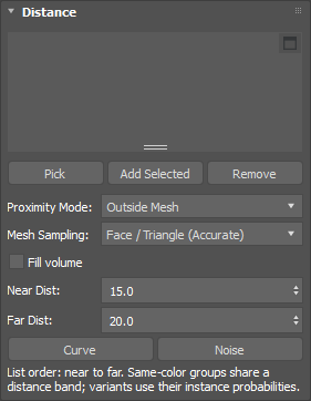
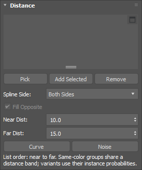
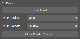
| Control | What it does |
|---|---|
| Object or spline list | Pick or add the references used for distance assignment. |
| Near / Far / Curve / Noise | Define and reshape the distance band. The source list runs from near to far; same-color groups share a band. |
| Mesh side / sampling / Fill volume | Choose mesh inside/outside handling, distance precision, and interior influence. |
| Spline Side / Fill Opposite | Choose spline side handling for a closed curve. |
| Start Paint / Brush Radius / Brush Falloff | Paint the selected source variants. Multiple selected sources are randomized per point. |
| Clear Painted Shapes | Clear the stored source-paint edits. |
Incoming sources and cluster coordinates
Refresh Diversity to inspect incoming instance geometry and source colors from SeaInstance or Point Instance. Disable palette rows to exclude them from assignment. Procedural clusters use local axes centered on all incoming points, and the default cluster map gizmo shares that center.
SeaCameraCull
On this page · 3 sections
Workflow
Choose the active view or pick a camera. Expand the culling view slightly to retain edge coverage. Add distance density or scale falloff when distant detail can be reduced.
All controls
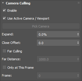
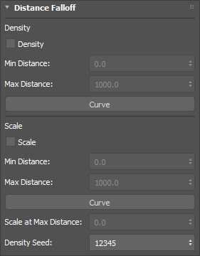
| Control | What it does |
|---|---|
| Enable / Target | Enable culling and select the incoming subset to process. |
| Use Active Camera / Viewport | Use the current view rather than a picked camera. |
| Pick Camera | Choose a scene camera. |
| Expand | Expand the viewing region used for culling. |
| Close Offset | Adjust the close boundary of the culling region. |
| Far Culling / Far Distance | Enable and set a far cutoff. |
| Only at This Frame / Frame | Evaluate the chosen view at a fixed frame. Animated cameras use that frame. |
| Update Frozen View | Capture the current free viewport for the frozen-view workflow. |
| Density / Min Distance / Max Distance / Curve | Reduce population through a distance transition. |
| Scale / Min Distance / Max Distance / Curve / Scale multiplier | Change size through the distance transition. Scale starts at 1 at Min Distance and reaches its multiplier at Max Distance. |
| Density Seed | Choose a stable random density pattern. |
Animation tip
Use a frozen frame to keep a consistent culled population while working. Use the animated camera when culling should follow the shot. Check reflections and shadows before relying on view-based removal.
SeaSelection
On this page · 4 sections
Workflow
Choose a Target rule, set how it combines with the incoming selection, and enable the outputs you need. Put this modifier below tools that use Selection (below), Named Selection Sets, or the written float channel.
Selection outputs
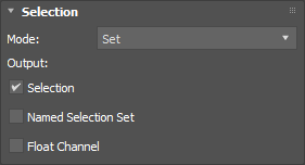
| Control | What it does |
|---|---|
| Target | Choose the source of the selection: geometric, painted, texture, data, source shape, or another shared Target mode. |
| Mode: Set / Add / Subtract | Replace, add to, or subtract from the incoming selection. |
| Output: Selection | Write the standard point selection. |
| Output: Named Selection Set | Write a reusable named set. Can be combined with the other outputs. |
| Output: Float Channel / Channel Name | Store soft-selection weights as a point float channel from 0 to 1. |
| Set Names: Custom Name / Set Name | Use a chosen name for the output set. |
| Set Names: Source Object Names | Use originating geometry or spline target names. Soft-selected points inherit the name of the nearest selected point. |
Soft selection
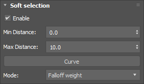
| Control | What it does |
|---|---|
| Enable | Extend influence beyond the fully selected core. |
| Min Distance / Max Distance | Weight is 1 at Min Distance and fades to 0 at Max Distance. Distances are measured from the nearest fully selected point. Partially selected points do not create new falloff origins. |
| Curve | Remap the distance-to-weight transition. Preview updates while editing. |
| Falloff weight | Pass calculated fractional weights through unchanged. |
| Falloff density | Use each weight as a stable probability of selecting the point; the result is 0 or 1. |
Selection Noise and Noise falloff
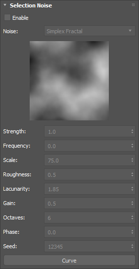
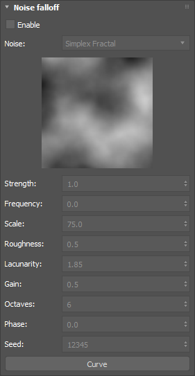
| Control | What it does |
|---|---|
| Enable / Noise | Enable each noise layer and choose Simplex, Simplex Fractal, Ridged Fractal, or Turbulence. |
| Strength | Displace selection sampling in scene units. Selection Noise breaks the target boundary; Noise falloff mainly displaces the outer falloff and preserves the core. Actual point positions do not move. |
| Scale | Pattern size in scene units. |
| Frequency | Evolution per second. 0 keeps noise static over time. |
| Roughness | Detail contributed by higher octaves. |
| Lacunarity | Frequency multiplier between octaves. |
| Gain | Amplitude multiplier between octaves. |
| Octaves | Number of overlapping patterns. Simplex uses one octave. |
| Phase / Seed | Evolution offset and deterministic pattern seed. |
| Curve / Preview | Remap normalized noise and inspect its pattern. The preview shows pattern independently of displacement amplitude. |
SeaVisualization
On this page · 6 sections
Workflow
Use a lightweight geometry mode and a reduced Viewport percentage while editing. Set Render independently. For diagnostics, choose a data channel and inspect its values through a color gradient.
Points
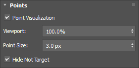
| Control | What it does |
|---|---|
| Point Visualization | Enable point display controls. |
| Viewport | Percentage of target points shown in the viewport. |
| Point Size | Point marker size in pixels. |
| Hide Not Target | Hide other points in the viewport. Disable to preserve their incoming display. Instance and rendering settings are separate. |
Instances
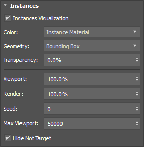
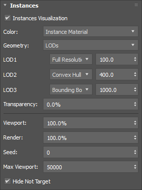
| Control | What it does |
|---|---|
| Instances Visualization | Enable instance display controls. |
| Color | Instance Material, Flat color, or Colors. |
| Geometry | Object Bounding Box, Bounding Box, Pyramid, Convex Hull, Full Resolution, or LODs. |
| LOD 1 / 2 / 3 | Choose None, Bounding Box, Pyramid, Convex Hull, or Full Resolution for each tier, and set its maximum camera distance. Beyond LOD3, instances are hidden. |
| Transparency | Viewport opacity: 0% is opaque and 100% invisible. Applies across geometry and color modes. Source shader transparency is used in Full Resolution. |
| Viewport / Render | Separate percentages of target instances for the viewport and rendering. |
| Seed | Stable ordering by point ID. The viewport and render percentages share that ordering, so smaller populations are nested subsets. |
| Max Viewport | Cap on target instances after Viewport %. Rendering uses Render % without this cap. |
| Hide Not Target | Hide instances outside Target in the viewport; disable to retain their incoming geometry display. |
Native Gaussian splat instances appear as bounding boxes in the SEA viewport.
Colors and channel inspection
| Control | What it does |
|---|---|
| Channel | Choose an incoming point channel. Color channels display directly; numeric and vector values use the gradient. |
| Space | Interpret transform channels in Local or World space for visualization. Stored data is unchanged. |
| Component | X, Y, Z, or Magnitude for vector values. |
| Min / Max | Value range mapped through the gradient. |
| Auto range | Use finite incoming minimum and maximum, including points outside Target. A constant channel uses the gradient midpoint. |
| Preset / Gradient | Choose a preset or edit color flags. Double-click changes a color; drag changes its position; right-click adds or removes a flag. End flags remain at 0% and 100%. |
Named selection sets are grouped under one heading.
Display versus data
Channel visualization changes appearance, not channel values. Viewport transparency does not rewrite materials. Rendering is controlled separately from point size, viewport LODs, and the viewport cap.
Stacked display and material opacity
Keep Hide no target off to retain incoming display outside a painted target when stacking SeaVisualization modifiers. Full Resolution uses source shader opacity and cutouts. Box, Pyramid, and Convex Hull proxies use the visualization transparency setting independently of source opacity.
SeaChannelEdit
On this page · 4 sections
Workflow
Choose Input and its Component, select an Operation and Operand, then choose Output. Use Clamp and Retarget to constrain or reshape the result. Restrict changes with Target.
Input and arithmetic
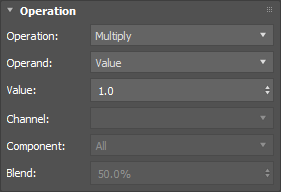
| Control | What it does |
|---|---|
| Input / Component | Choose a channel and All, X, Y, Z, or W. None input starts from zero and requires an explicit output channel. |
| Operation | Multiply, Add, Subtract, Blend, Divide, or Set. Set writes the operand directly. Blend interpolates toward it. Division by zero preserves the incoming value. |
| Operand: Value | Use the numeric Value field. |
| Operand: Channel | Read another channel and select its component. |
| Operand: By proximity mesh | Calculate an operand from distance to reference meshes. |
| Operand: By proximity spline | Calculate an operand from distance to reference splines. |
| Operand: By map | Calculate an operand from map brightness. |
| Blend | Interpolation amount for the Blend operation. |
Proximity and map operands
| Control | What it does |
|---|---|
| Pick / Add / Remove | Manage reference meshes or splines. |
| Near Dist / Far Dist / Curve | Map distance to the operand value. Curve X is 0 at Far and 1 at Near. |
| Mesh Sampling | Vertex (Fast), Face / Triangle (Accurate), or Hybrid (Balanced). |
| Mesh Side / Fill volume | Outside Mesh, Inside Mesh, or Both Sides; Fill volume makes interior influence full. |
| Spline Side / Fill opposite side | Both Sides, Outside Only, or Inside Only, with optional opposite-side fill. |
| Map / Mapping | Choose a native map or drag one from the Material Editor. Use UVs or Texture Gizmo. |
| Multiplier | Multiply map brightness. Values over 1 amplify it. |
Clamp, Retarget, and Output
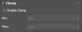
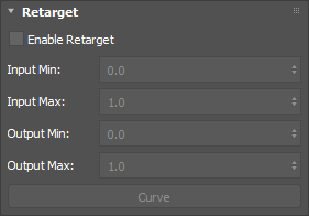
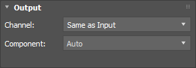
| Control | What it does |
|---|---|
| Enable Clamp / Min / Max | Clamp the arithmetic result to the chosen range. |
| Enable Retarget | Normalize after arithmetic and Clamp, apply the remap curve, then map to the output range. |
| Input Min / Input Max | Normalization range for Retarget. |
| Output Min / Output Max | Final remapped value range. |
| Curve | Normalized input-to-output remapping. Values outside the input range hold the curve’s endpoint values. |
| Output | Choose an existing channel or type a new name. Same as Input edits the incoming channel. A new channel inherits the whole input type; a selected component creates a float channel. |
| Output Component | Auto, All, X, Y, Z, or W determines where the result is written. |
SeaConvertToInstances · Modifier
On this page · 3 sections
Workflow
Apply the modifier to an existing mesh object. Enable Convert by element if each separate mesh element should become its own placement. Add point modifiers above it to edit the resulting system.
All controls
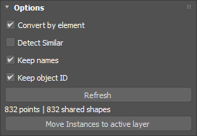
| Control | What it does |
|---|---|
| Convert by element | Split the incoming mesh into elements before conversion. |
| Detect Similar | Share matching geometry, including repeated elements, while accounting for transforms and pivot differences. |
| Keep names | Store source names as point named selection sets. |
| Keep object ID | Store source-based ObjectID data on the converted points. |
| Refresh | Rebuild conversion from the incoming result. |
| Move Instances to active layer | Expose or move the actual shared shapes to the active scene layer. |
| Status | Read conversion results or errors. |
Related object
Use the object version when you need a list of several scene sources, World/Local placement options, or Hide source objects.
SeaExtract
On this page · 3 sections
Workflow
Choose Target and the frame range, inspect the extraction summary, then use Extract. This is an explicit scene operation: it creates nodes when you request extraction. Normal stack evaluation does not create scene nodes.
All controls
| Control | What it does |
|---|---|
| Target | Choose which points should be extracted. |
| Min / Max | Inclusive frame range. Use the same frame for a static extraction; a range samples animated transforms. Max must be at least Min. |
| Apply target as selection | Also apply the target as point selection. |
| Hide extracted | After successful extraction, hide the source points and their instances to avoid duplicates. Disable to reveal them again. |
| Extract | Prepare the operation and create nodes after the tool’s confirmation. |
| Status / Summary | Inspect the planned instance and helper population and frame count. |
Result
Extracted geometry uses shared source instances and is added to the active layer. Points without geometry can become point helpers. Animated extraction samples transforms and visibility over the requested range. A large population across many frames can create substantial scene data, so test a small target first.
SeaIsolate
On this page · 3 sections
Workflow
Choose Target and enable Isolate to focus on that subset. Use Match Bounds when the targeted assembly needs to align or fit a reference object or explicit target box.
Isolate and reference

| Control | What it does |
|---|---|
| Target / Isolate | Choose and isolate a subset of the incoming point system. |
| Enable Match Bounds | Enable alignment and fitting. |
| Mode | World or Local bounds calculation. |
| Pick Reference Object / Clear | Use another object’s bounds or clear the reference to enter target bounds manually. |
Position, Rotation, and Scale
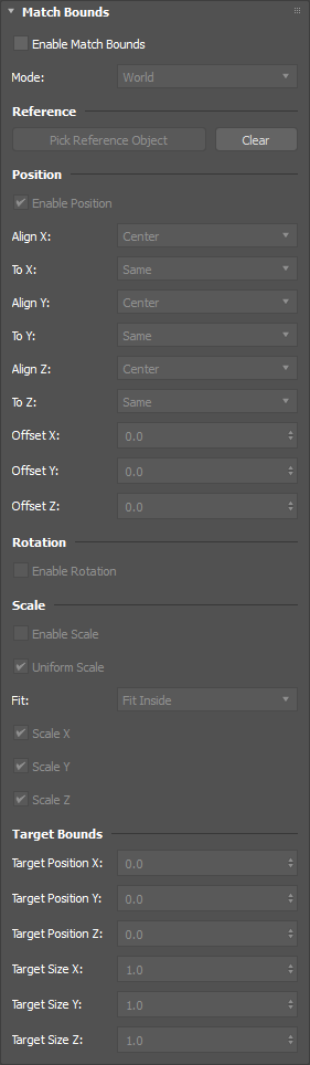
| Control | What it does |
|---|---|
| Enable Position | Enable bounds position alignment. |
| Align X/Y/Z | Choose None, Min, Center, or Max on the source bounds. |
| To X/Y/Z | Align to Same, Min, Center, or Max on the destination bounds. |
| Offset X/Y/Z | Add a positional offset after alignment. |
| Enable Rotation | Enable reference rotation matching. |
| Enable Scale | Enable bounds fitting. |
| Uniform Scale | Preserve proportions with one fit factor. |
| Fit | Fit Inside, Fill Outside, X, Y, Z, Bounds Perimeter, Bounds Area, or Bounds Volume. |
| Scale X/Y/Z | Enable independent fit axes when uniform scale is off. |
| Target Position X/Y/Z / Target Size X/Y/Z | Define an explicit target box when no reference is selected. |
SeaLeaning
On this page · 3 sections
Workflow
Choose Target, add support geometry to Lean towards geometry, and enable the modifier. Inspect the actual instance size and source pivot because these determine contact. Use the out-of-reach set to find unsupported placements.
All controls
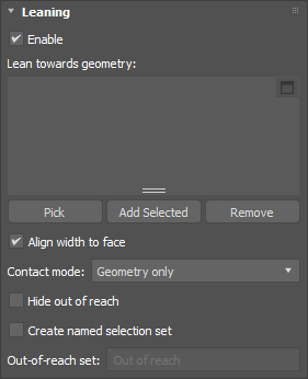
| Control | What it does |
|---|---|
| Enable / Target | Activate the leaning result on the chosen subset. |
| Lean towards geometry: Pick / Add Selected / Remove | Manage support references. |
| Align width to face | Align the wider transverse bounds axis parallel to the supporting face before leaning. Uses scaled bounds and the nearest equivalent facing direction. |
| Contact mode: Geometry only | Use mesh support geometry. |
| Contact mode: Bounding boxes (lean on instances) | Allow contact with neighboring instance bounds and lift the displayed instance enough to clear its distribution surface. Scatter point positions and source pivots stay unchanged. |
| Hide out of reach | Hide instances that cannot reach support. |
| Create named selection set | Write membership for unsupported instances, including hidden out-of-reach points. |
| Out-of-reach set | Name of that selection set. A blank field uses Out of reach. |
Ground and neighbor contact
Bounding-box contact accounts for source pivot offsets and the distribution surface. A piece that cannot reach support without intersecting neighbors at its fixed position is marked out of reach. Use Hide out of reach or the named selection set to inspect blocked placements.
SeaPackUnpack
On this page · 3 sections
Workflow
- Add this modifier to a nested point system, such as a PointRef assembly.
- Choose Unpack and set Levels to expose the desired depth.
- Add selections and edits above the unpacked level.
- Add another Pack / Unpack modifier set to Pack when you want to restore recorded parent levels.
All controls
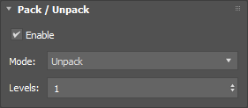
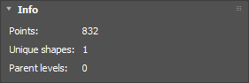
| Control | What it does |
|---|---|
| Target | Choose the nested placements or points to process. |
| Enable | Turn hierarchy processing on or off. |
| Mode: Unpack | Expose deeper point levels. |
| Mode: Pack | Restore recorded parent levels, or group targeted points if there is no recorded parent hierarchy. |
| Levels | Number of levels to process, from 1 to 16. |
| Info: Points | Point count at this modifier’s output, including disabled points. |
| Info: Unique shapes | Distinct sources used at this level, including disabled points. Geometry nested inside a source belongs to a deeper level. |
| Info: Parent levels | Recorded parent levels available to pack. Parent 1 is the nearest parent. |
| Parent level / Groups | Group counts for each recorded parent level. |
Why this matters
Unpack exposes the nested point structure without baking all geometry into unique meshes. Check the Info rollout to confirm which level you are editing before targeting a component set.
SeaInstance
On this page · 2 sections
Instances and probabilities
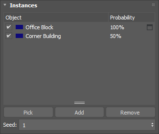
Choose Target, then Pick, Add, or Remove geometry in Instances. The list initializes from incoming instance sources. Source swatches follow the original wire colors. Each enabled source starts at 100% probability. Values are relative weights and zero excludes a source. Seed makes assignments repeatable. Select several rows to edit their values together. Dynamic rule values apply to current and future matches.
Assignment behavior
An empty source list preserves incoming instances. A list with all weights at zero clears instances on targeted points. Assignments preserve point IDs, transforms, and channels. SeaClusters reads the resulting source palette directly.
SeaPushPull
On this page · 2 sections
Sources, direction, and falloff
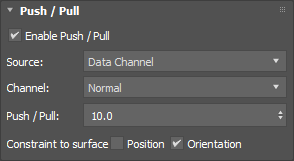
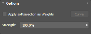
Choose Target and a Mesh geometry or Splines source list. Pick or add reference objects. Set a signed displacement and shape the influence using Min and Max distance and the curve. Spline distance uses 3D positions. Ignore negative values supports outward displacement along a mesh normal for inside points.
Choose Data Channel to use a Point3 direction for each incoming point. Set the signed Push / Pull amount, then use Strength and Apply softselection as Weights under Options to control the influence.
Surface constraints and Physics
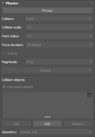
Use Position to constrain points to their original distribution surface and Orientation to follow its normal. Physics applies the force continuously for the chosen frame count. Select Point, Box, or Convex hull collision, choose surface and explicit colliders, and adjust gravity and motion limits in the shared Physics controls.
While scrubbing, Push/Pull reuses cached physics results when the simulation inputs stay the same.
Target & selection
On this page · 7 sections
Target modes

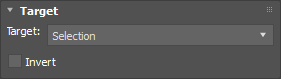
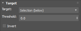
| Control | What it does |
|---|---|
| All | Affect the entire incoming population. Use this when creating new points with a brush. |
| Selection | Use points selected in this modifier’s Point subobject level. |
| Selection (below) | Use the selection entering from lower in the stack. |
| Named Selection Sets | Use stored point sets. |
| Data Channel | Choose points by a numeric, vector, integer, or color channel test. |
| By Object Proximity | Use distance to reference geometry. |
| By Curve Proximity | Use distance to reference splines. |
| Paint | Paint a persistent target region. |
| Texture | Use map brightness as target influence. |
| By Points | Use reference point centers or instance footprints. |
| InstanceShape | Choose one or more incoming instance-source slots. |
Selection and named sets
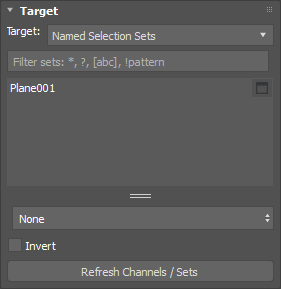
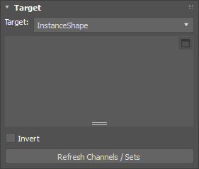
| Control | What it does |
|---|---|
| Threshold | 0 includes hard-selected points only. Increasing it includes weaker soft weights; 1 includes every point with positive weight. Unselected points remain excluded. |
| Set list | Choose the named sets you want to target. |
| Filter sets | Use * for any text, ? for one character, [abc] for listed characters, and !pattern to exclude. Separate patterns with semicolons. Matching ignores case. |
| Index | 1-based position among visible filtered sets. 0 means no current visible entry. |
| InstanceShape list | Select source slots. IDs are zero-based as in Point Instance; the internal default pyramid is excluded. |
Data Channel
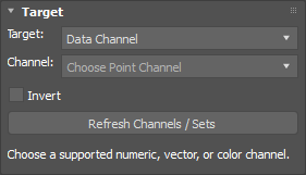
| Control | What it does |
|---|---|
| Channel | Choose an incoming Point channel. |
| Space | Local tests stored coordinates. World includes the scatter transform: positions include translation, vectors include rotation/scale, and rotations use XYZ degrees. UVs remain texture coordinates. |
| Axis | X, Y, Z, Magnitude, or Dot Product. |
| Min / Max | Inclusive bounds for the chosen numeric value or component. |
| Values | Enter integer IDs or ranges, such as 1,2,5 or 1-7. |
| Reference Z | For Dot Product, pick an object or helper. Its normalized world Z axis is the reference. |
| Dot Min / Max | Inclusive alignment bounds. Incoming vector magnitude is retained, so values can exceed 1. |
| Color: Hue / Intensity | Compare color hue or average RGB intensity. |
| Match Color / Similarity | Choose the reference color and tolerance. 0% matches exactly; 100% accepts all hues or intensities. |
Object, curve, and point proximity
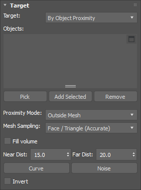
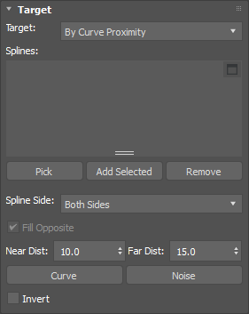
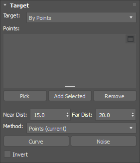
| Control | What it does |
|---|---|
| Reference list / Pick / Add / Remove | Manage the geometry, splines, or point references. |
| Near / Far Distance | Full selection influence through Near, zero at Far. Curve shapes the transition. |
| Curve / Noise | Remap proximity or displace sampling distance. Curve X runs from 0 at Far to 1 at Near; Y is selection weight. Noise does not move actual points. |
| Proximity Mode | Outside Mesh, Inside Mesh, or Both Sides. |
| Mesh Sampling | Vertex (Fast), Face / Triangle (Accurate), or Hybrid (Balanced). |
| Fill volume | Give interior mesh points full influence. |
| Spline Side / Fill Opposite | Both Sides, Outside Only, or Inside Only, with optional opposite-side fill. |
| Points Method | Points (current) uses 3D center distance. Geometry aware (top view) uses actual mesh footprints in world XY and ignores height. |
| Footprint Resolution | 64–4096 px on the longest map side. More detail uses more memory and rebuild time. |
Paint and Texture targets
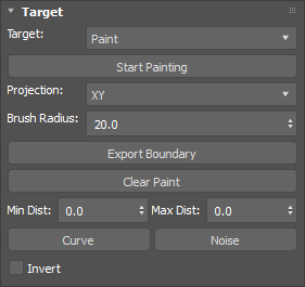
| Control | What it does |
|---|---|
| Paint: Start Painting / Radius | Left drag adds area; Shift subtracts; Ctrl + Alt + left drag changes radius. |
| Paint Projection | XY, XZ, YZ, or Screen Space. Screen Space captures a persistent view-plane orientation when painting starts. |
| Paint Min / Max | Signed distance from boundary where weight reaches 0 and 1. Positive is inside. Equal values produce a hard boundary. |
| Export Boundary / Clear Paint | Export the mask boundary or clear the stored target paint. |
| Texture map / Browse / Clear / Refresh | Choose a preset, image, or custom native map; clear it or refresh its preview and sampled data. |
| Mapping | UVs uses the map’s assigned channel. Texture Gizmo uses the viewport projection. |
| Threshold | Set the grayscale cutoff on its own row. The default is 50%. Within valid texture coverage, points pass when sampled brightness meets or exceeds the cutoff. |
| Link X/Y / Dimensions / Offsets / Rotation | Control the visible coordinate fields in UV mode. Dimension X/Y are tile extents there. |
Invert and weights
Invert reverses the target result. A target chooses eligibility; a modifier’s weight option determines whether fractional influence is used. For example, enable weights in SeaModify to blend transforms through a proximity or texture target.
Paint falloff and texture projection
Target Paint has its own Inside/Outside setting. Outside retains full influence inside the painted boundary and fades outward. Texture mapping uses UVs or Texture Gizmo. UV dimensions begin at 1 × 1 and are stored separately from gizmo dimensions. Use the stack’s Texture Gizmo subobject to position the projection.
On modifiers with Target Outputs, enable Selection to write the target membership to the active point selection, Named Selection Set to store the membership under a name, or Gradient (0–1) to write the target weights to a channel. SeaFilters also has Keep all points for exporting the combined mask without removing rejected points.
Painting & Physics
On this page · 8 sections
Start, finish, and shortcuts
Click Start Painting to enter the viewport tool. Right-click or press Enter to finish; Tab cycles brush modes while painting. Ctrl + Alt + left drag adjusts radius. Alt + left drag adjusts creation Z offset. Modifier keys can have brush-specific behavior; use the tool’s current mode when interpreting a stroke.
Brush modes
| Control | What it does |
|---|---|
| Create | Place points. Strength is the probability of placing each candidate; Shift erases and Ctrl relaxes. |
| Erase | Hide a percentage of points per brush dose. Hold to keep trimming; Shift restores. Falloff reduces influence at the brush edge. |
| Push/Pull | Push points apart; Shift pulls them together; Ctrl relaxes. |
| Relax | Smooth local point spacing. |
| Scale | Apply Add, Multiply, Replace, or Subtract. Scale Value is a delta, factor, or target depending on operation. Shift reverses Add/Subtract. |
| Move | Move the affected points with a drag. |
| Smudge | Move points by a percentage of mouse travel, multiplied by brush falloff. |
| Data Channel | Paint an incoming numeric or color channel. Choose Channel, Axis (X/Y/Z/W/All), Operation (Add/Set/Multiply), Value, or Color. Ctrl averages components independently. Refresh Channels reloads the available list. |
| InstanceShape | Paint chosen source variants onto existing points. Refresh Shapes updates the source palette. Multiple choices are randomized. |
| Chaos | Agitate the affected points. Choose 1 Kick or Continuous Chaos, enable the available agitation components, and set their strengths. Continuous mode keeps agitating while held, including physics substeps. |
Brush settings
| Control | What it does |
|---|---|
| Radius | Outer brush radius. |
| Falloff | Inner falloff region controlling transition toward the outer brush edge. |
| Density | Number of candidate points per stamp. |
| Spacing | Minimum spacing while creating points. |
| Strength | Influence of Push/Pull and Relax, or creation probability. Smudge has its own percentage of mouse travel. |
| Erase % | Percentage hidden or restored with each dose, from 0–100%. |
| Brush Shape | Circle, Square, or Sphere. |
| Projection | XY, XZ, YZ, or Screen Space fallback plane. Surface hits take priority. |
| Position / Orientation | Constrain point origins to the recorded surface and optionally align instance orientation to its normal. |
| Force snap | Prefer point hits over surface hits. With this off, point hits are used only if no surface is hit. |
| Preview Points | Show point previews while working. |
| Clear Strokes | Remove the stroke history stored in this object or modifier. |
Creation and Instanced Geometry
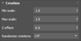
| Control | What it does |
|---|---|
| Min scale / Max scale | Random scale range for new points. |
| Randomize rotations | Off, All axes, or Z axis. |
| Z offset | Offset new points along the painted surface normal. Negative values move into the surface. |
| Sources: Incoming/Default | Use the incoming instance sources or default geometry. |
| Sources: From list | Use the explicitly managed geometry list. |
| Sources: Pick Geometry | Choose geometry through the picking workflow. |
| Pick / Add Selected / Remove | Manage the source list. |
| Source selection | Selected sources are randomized per point. No selection uses every listed source. During a held stroke, move over an expanded list entry to switch geometry, then return to the viewport. Earlier strokes retain their sources and colors. |
Physics
| Control | What it does |
|---|---|
| Physics | Enable collision simulation for brush edits and creation settling. |
| Collision | Point, Box, or Convex hull. |
| Collision scale | Multiply collision shape size without changing visible geometry size. |
| Point radius | Scene-unit radius, further multiplied by point scale, object scale, and Collision scale. |
| On create apply it for | Settle only newly created points after release for this number of scene frames. 0 skips settling. |
| Gravity / Magnitude | Downward world-Z acceleration in scene units per second squared. Surface Position constraints remain active with Gravity. |
| Use scene objects | Also collide with geometry visited by the brush. Create remembers surfaces touched during the stroke. |
| Collision objects: Pick / Add / Remove | Manage additional colliders. |
| Geometry: Convex hull | Use solid hulls, placed separately for each point-system instance with its transforms and offsets. |
| Geometry: Mesh | Use triangles, preserving holes and concave surfaces. |
Physics Options
| Control | What it does |
|---|---|
| Simulation speed | Time multiplier for held simulation, 0.1–10×. Default is 3×. It does not multiply gravity or change Create frame duration. |
| Linear drag | Damp translational motion; 0 disables drag. Units are inverse seconds. |
| Angular drag | Damp rotation when orientation is unconstrained. |
| Max speed | Limit linear velocity in world scene units per second. |
| Max spin | Limit angular velocity in degrees per second. |
| Separation speed | Limit overlap-correction velocity. Lower values reduce explosive separation impulses. |
Replay and identity
Physics and source settings are captured for new strokes. Editing an option does not necessarily resimulate earlier strokes. The Paint modifier’s Strength controls overall edit influence; its ID field chooses particle matching. Use a stable unique ID channel for animated caches when available.
Surface position, orientation, and shortcuts
In Brush Settings, use Position to project touched points onto their recorded surface, including during Physics with Gravity enabled. Orientation aligns instances to the surface normal while preserving heading and scale. The viewport shortcut legend follows the active brush and Max key assignments.
Maps, curves & noise
On this page · 4 sections
Map slots
| Control | What it does |
|---|---|
| Choose map | Click a map slot to browse its presets or native map picker. Where supported, drag in an image or a Material Editor map. |
| Right-click | Browse or clear the map. Some map controls also expose coordinate options. |
| UVs | Use the UV channel assigned in the map. Prepare suitable source UVs before using this mode. |
| Texture Gizmo | Use the stack gizmo as the projection. Select the corresponding Texture Gizmo subobject and use Max Move, Rotate, and Scale. |
| Dimension X/Y | Projection width and height in the visible coordinate workflow. UV dimensions describe tile extent; world projection dimensions use scene units. |
| Link X/Y | Use the same dimensions on both axes. |
| Offset X/Y / Rotation | Translate and rotate map coordinates. |
| Strength / Weight | 0% removes map influence, 100% applies it fully. The map drives the operation it belongs to: density, selection, transform variation, or an operand. |
| Refresh Map | Resample external or changed map content. |
Interpreting brightness
SeaPointDistribution and SeaFilters Texture use a brightness cutoff after inversion. On a SeaFilters Texture entry, brightness is tested against Threshold after Invert; Tileable determines whether the mask repeats or is limited to one footprint. For transform ranges, black maps to Min and white maps to Max. For Target, brightness supplies selection weight. For ChannelEdit, brightness becomes an operand and Multiplier can amplify it.
Curves
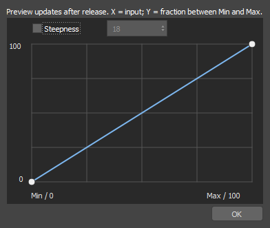
Curves remap a normalized input into an output weight. Read the axis hint in the dialog: proximity curves use X = 0 at Far and 1 at Near; selection falloff uses normalized distance; Retarget uses normalized channel value. A straight rising line preserves the normalized input. Bend it to sharpen, flatten, or delay a transition.
Where Steepness is offered, enable it and choose the number of output intervals to quantize the result. For example, 18 steps across a 0–360° range produces 20° increments.
Noise controls
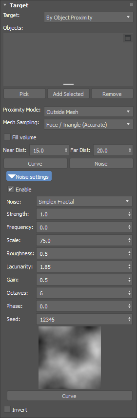
Noise displaces mask or selection distance sampling without moving points. Enable the noise, then choose Simplex, Simplex Fractal, Ridged Fractal, or Turbulence where offered. Scale sets feature size; Strength sets distance displacement; Octaves, Roughness, Lacunarity, and Gain shape detail. Seed changes the repeatable pattern; Phase shifts evolution; Frequency animates evolution per second. A frequency of 0 is static. The remap Curve adjusts contrast.
Workflow & troubleshooting
On this page · 7 sections
Nothing appears
Check the surface or cache path, point count, active distribution mode, and source size. Temporarily disable masks and culling, use Target: All, and inspect the result with a simple pyramid or bounding-box display. A default pyramid is a point preview rather than your final source geometry.
My modifier affects the wrong points
Check Target and stack order. Selection means this modifier’s own Point subobject selection; Selection (below) means incoming selection. Verify named-set filters and InstanceShape indices. Use Visualization to inspect channel values before building a Data Channel target.
The texture or proximity mask looks wrong
Check UVs versus Texture Gizmo, projection scale, map Strength, Invert, reference lists, and Near/Far distances. Geometry-aware point proximity is a top-view XY footprint and ignores height; use point-center distance when you need a 3D center test.
Instances intersect or float
Check source pivot, bounds, instance scale, creation offset, and the placement of KillOverlaps in the stack. Increase collision precision only as needed. For physics, check touched surfaces or explicit colliders, collision scale, Gravity, and Constraint orientation. Sparse leaf cards may need lower Density Profile density.
Painting changes when the source updates
Use a stable unique particle ID in the Paint modifier. Index follows ordering, and missing or duplicate matching keys are skipped. Keep required source geometry and referenced files available.
The viewport is slow
Use Visualization’s Viewport percentage, Max Viewport, and bounding-box or LOD display. Keep Render percentage appropriate to the final shot. Read every in Loader reduces imported points; visualization limits only change display. High footprint resolution, profile quality, ray samples, and complex physics colliders all increase work.
A referenced assembly is difficult to edit
Use PointRef’s stored name/material/group sets. Add Pack / Unpack to expose deeper levels, then target the desired parts. Inspect its Points, Unique shapes, and Parent levels before editing or packing again.
Dynamic source lists
On this page · 3 sections
Add and edit a rule
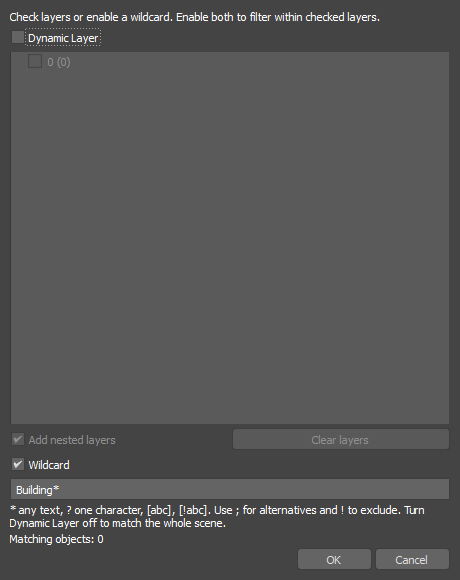
Right-click Pick or Add and choose Dynamic. Enable Dynamic Layer and check layers in the tree. Add nested layers includes descendants. Enable Wildcard to match scene names. When both switches are enabled, names must match within the checked layer scopes. Double-click a rule in either list view to edit it. Disabled scopes retain their settings.
Wildcard syntax and live membership
Matching ignores case. Use * for any text, ? for one character, [abc] for a character set, and [!abc] for its complement. Separate alternatives with semicolons and prefix exclusions with !. A rule such as Cars*; !Cars_old* includes car names and excludes the old set. Rules follow scene edits and layer renames, deduplicate overlapping references, and count eligible sources. Hidden geometry remains eligible. Private internal nodes and dependency cycles are excluded.
Enable, disable, and edit selected rows
Use the checkbox to pause a source or rule while retaining its order, references, and values. Clicking the checkbox of a selected row applies the change to all selected rows in one undo step. An unselected row changes on its own. Compact and expanded editors support the same selection behavior. In SeaPacking and SeaInstance, selected-row value edits also work with a mix of direct objects and dynamic rules.
Shift-click includes disabled rows in the selected range. Batch visibility changes can apply to those rows as well.